详细说明
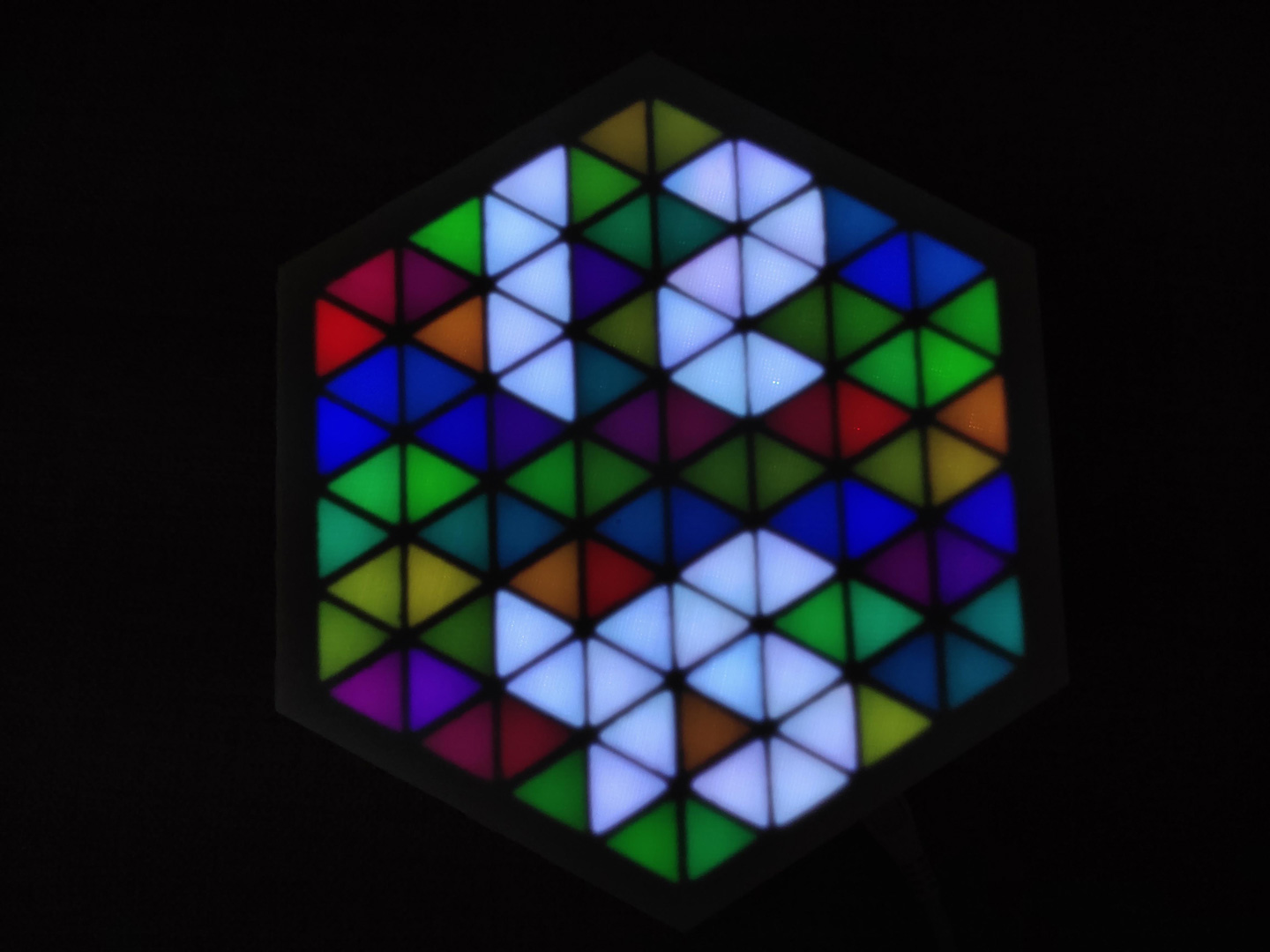
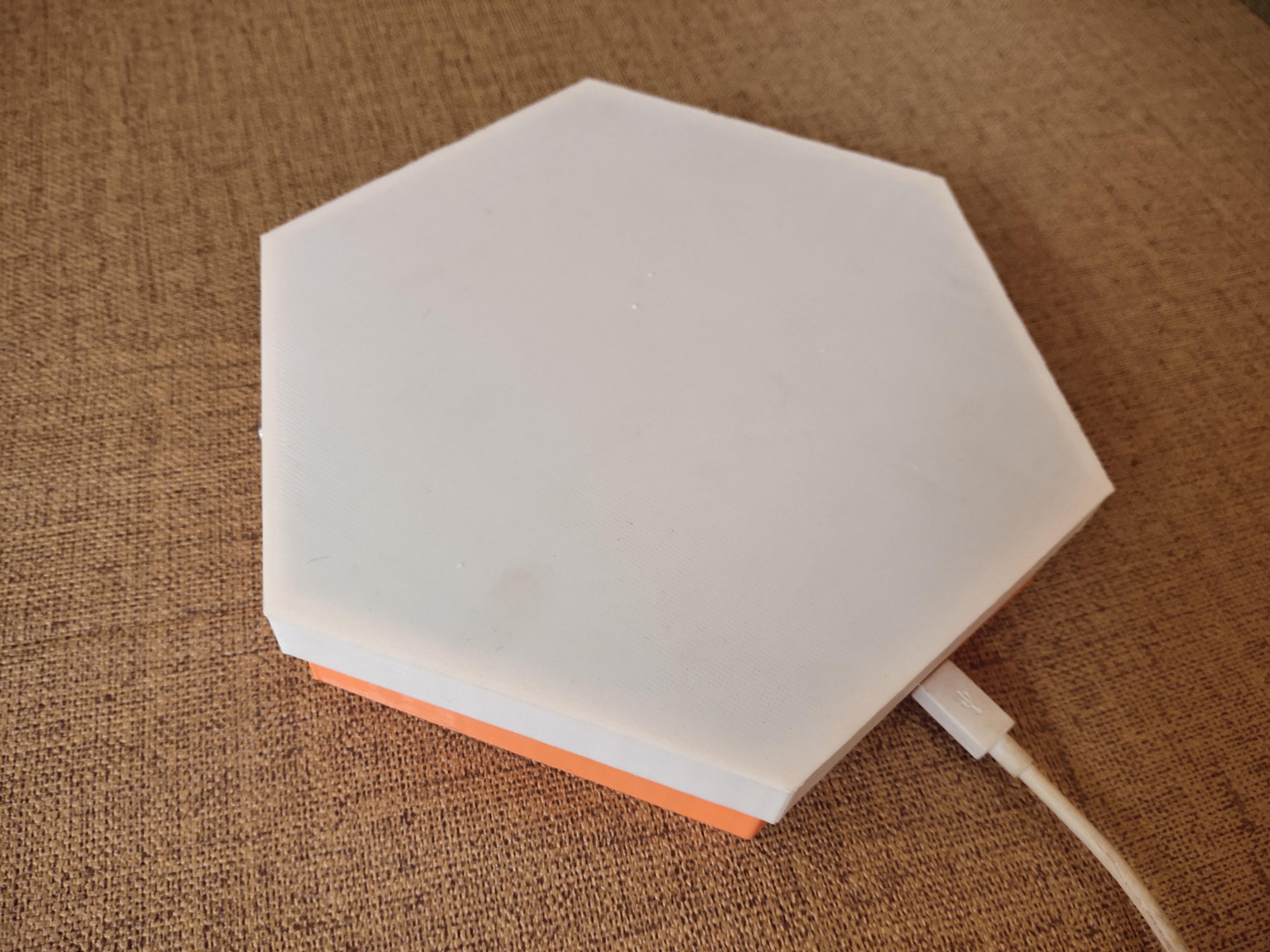
HexMatrix 2.0 是对之前 HexMatrix 的升级。
HexMatrix 1.0 项目主页:https://make.quwj.com/project/306
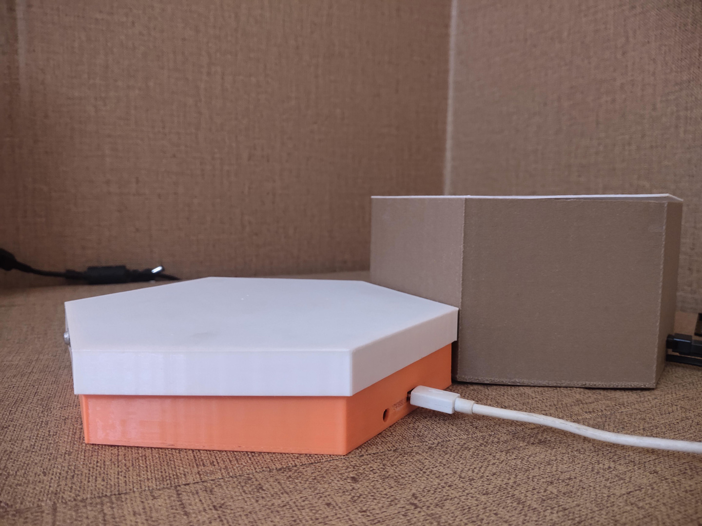
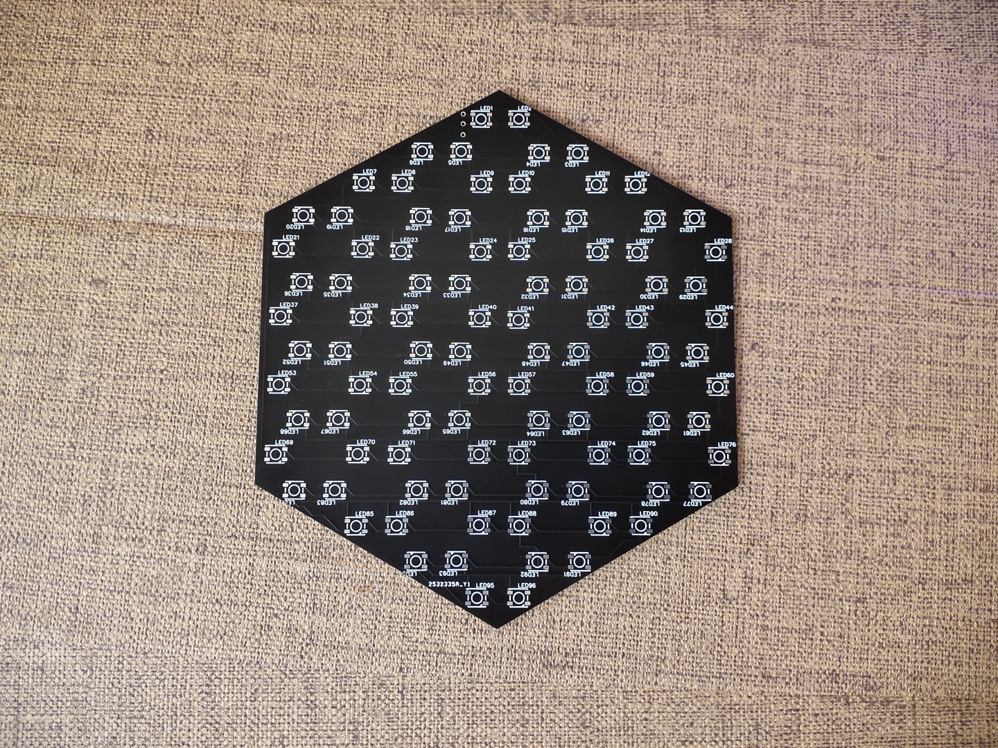
之前就有朋友想到用专门设计的 PCB 来简化电路的制作,新版本就实现了这个部分,使点阵的厚度减少了 3 厘米。
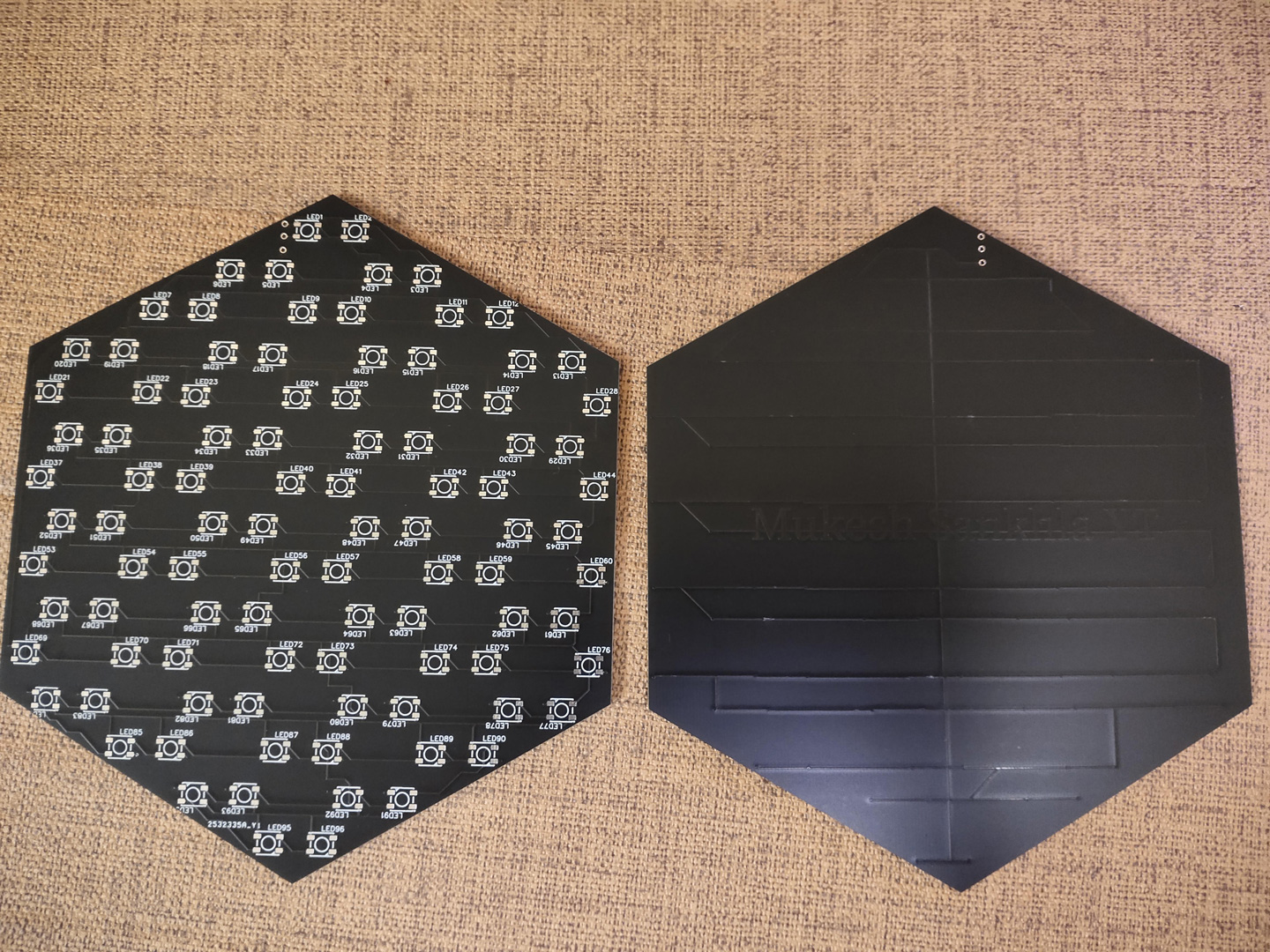
PCB 文件在项目文件库中提供下载:
https://make.quwj.com/project/338
链接表
文件库
Case.stl
[17684 Bytes at 2020-09-19, 116 次下载]
Ring.stl
[3684 Bytes at 2020-09-19, 98 次下载]
Screen.stl
[1084 Bytes at 2020-09-19, 82 次下载]
HexMatrixC.png
[87522 Bytes at 2020-09-19, 101 次下载]
Gerber_NEW_PCB.zip
[79061 Bytes at 2020-09-19, 116 次下载]
Matrix.stl
[106084 Bytes at 2020-09-19, 100 次下载]
HexClock2.0.ino
[37651 Bytes at 2020-09-19, 189 次下载]
教程
材料清单
PCB Gerber 文件可在本项目文件库下载:
https://make.quwj.com/project/338
NodeMCU(ESP8266)
WS2812B LED 若干
5V 2A micro USB 电源
3D 打印部件
3D 打印部件
STL 文件可在本项目文件库下载:
https://make.quwj.com/project/338
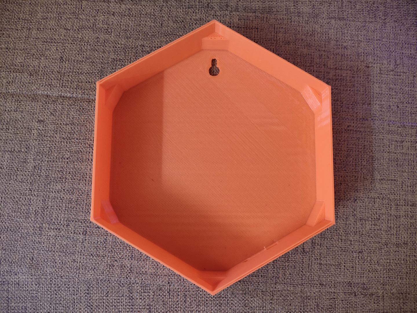
3D 打印所有的文件,其中屏幕前端使用白色 PLA 材料。


连接电路
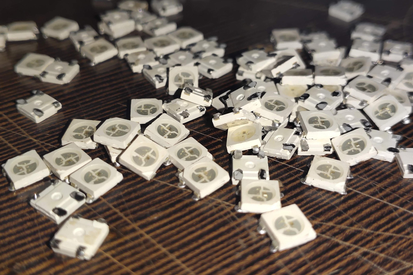
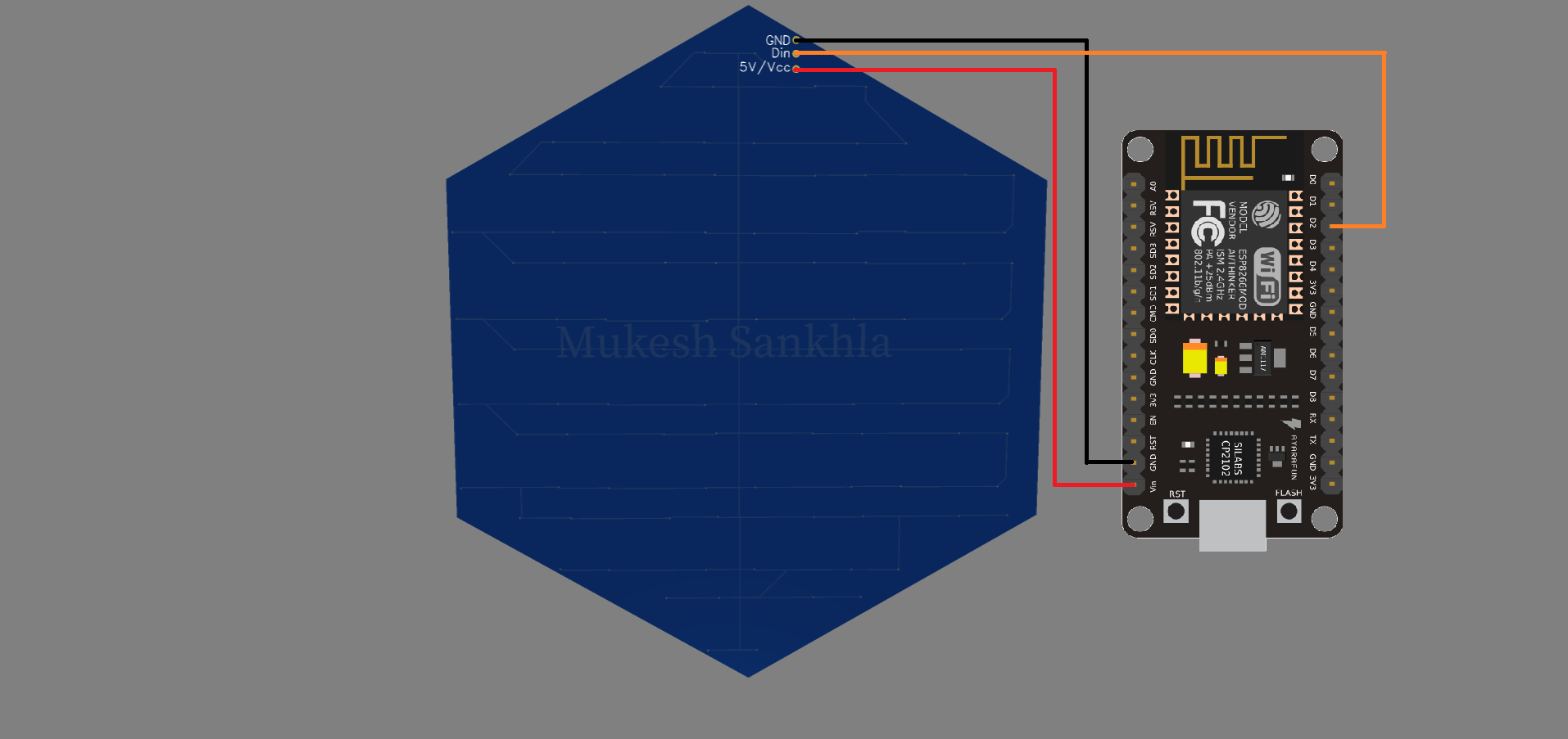
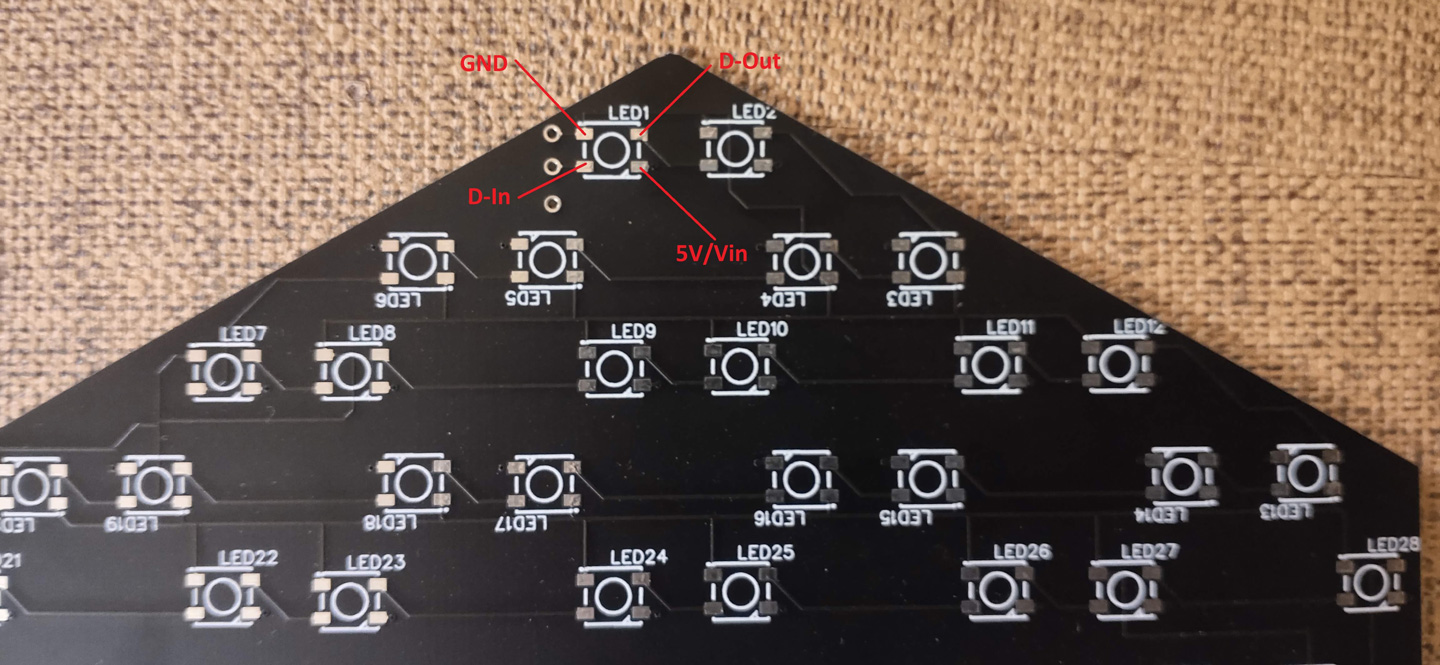
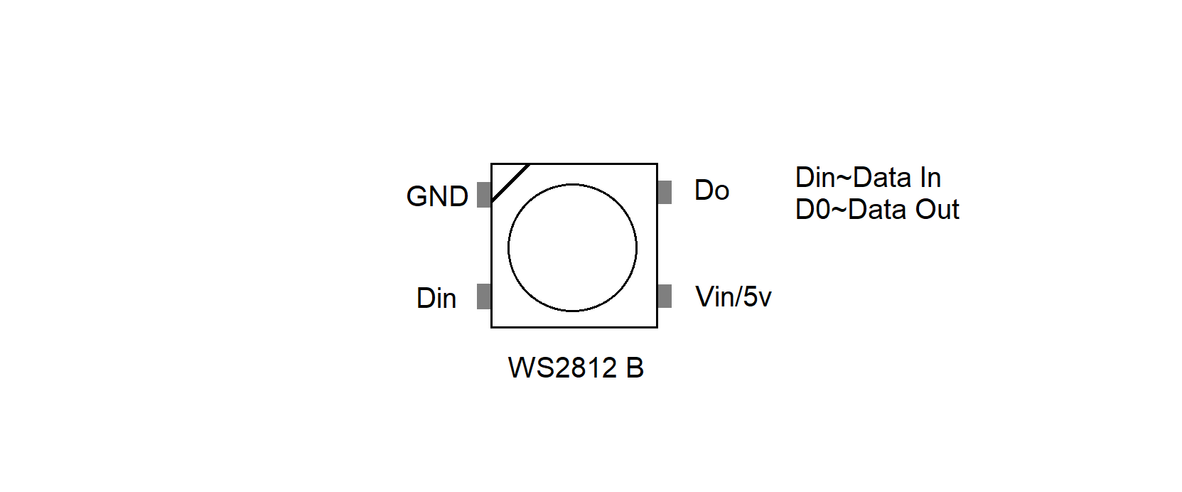
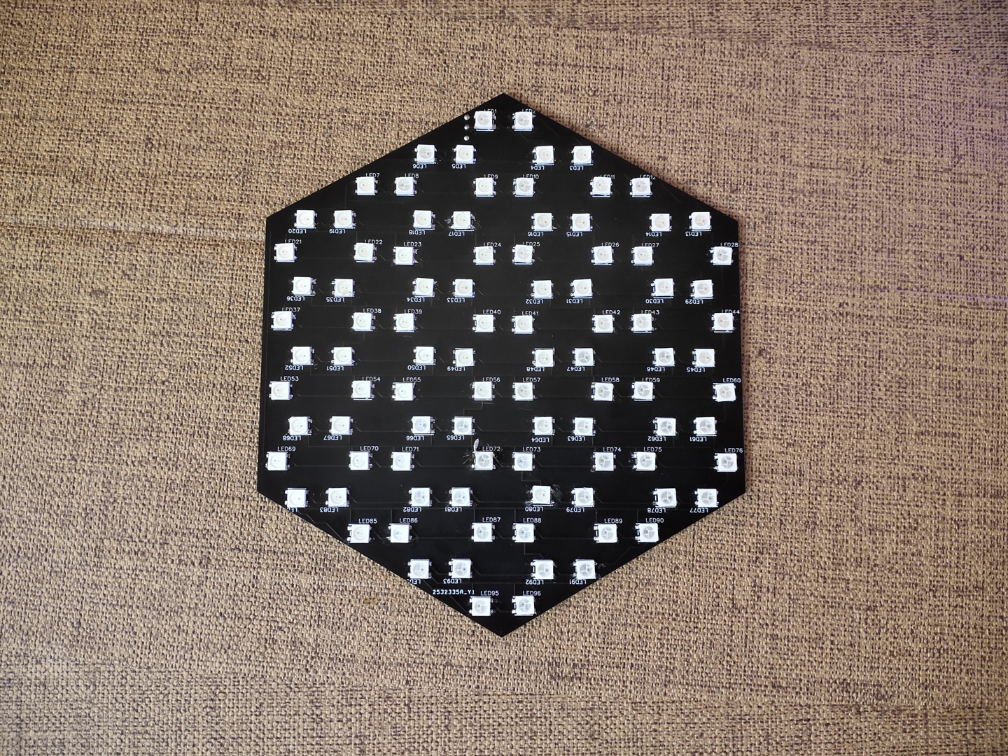
将 LED 灯珠焊接到 PCB 上。请参考下面的电路图,注意极性。
GND~GND
Vin~5V
D2~Din
编程
代码文件可在本项目文件库下载:
https://make.quwj.com/project/338
打开 Arduino IDE。
安装 FastLED 库以及 ESP8266 开发板所用的库。
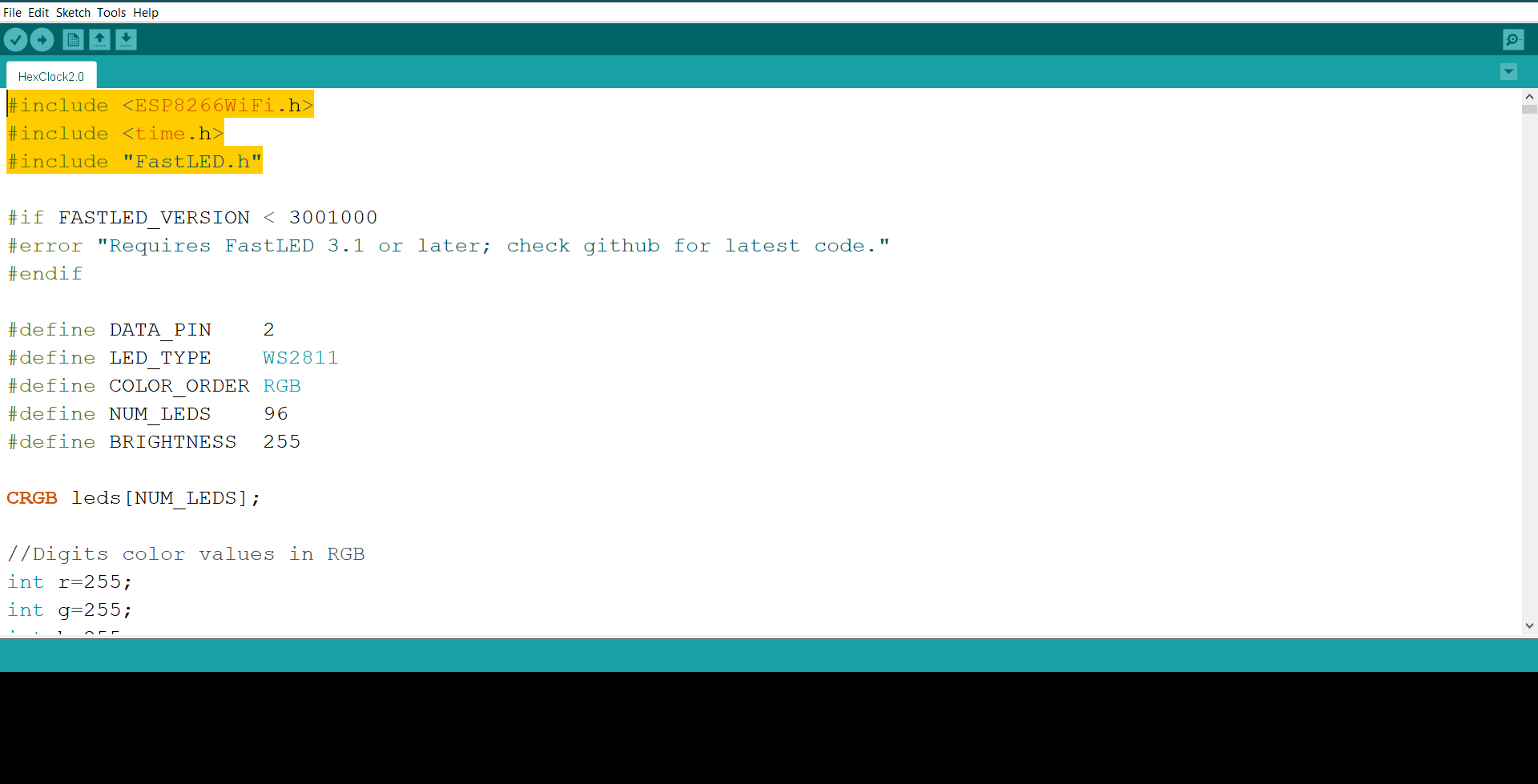
修改代码中的 WIFi 信息。
//Your Wifi info
const char* ssid = "Wifi_Name";
const char* password = "Password";

修改你所在的时区
//Your time zone
int timezone = 5.5 * 3600;
选择开发板类型为 ESP8266 (NodeMCU),再选好 ESP8266 和 PC 连接的端口并上传代码。
上传完成之后,请使用 micro USB 电源来供电,测试点阵是否被点亮。FastLED 库中还有一些动画效果可以进一步测试。
完成
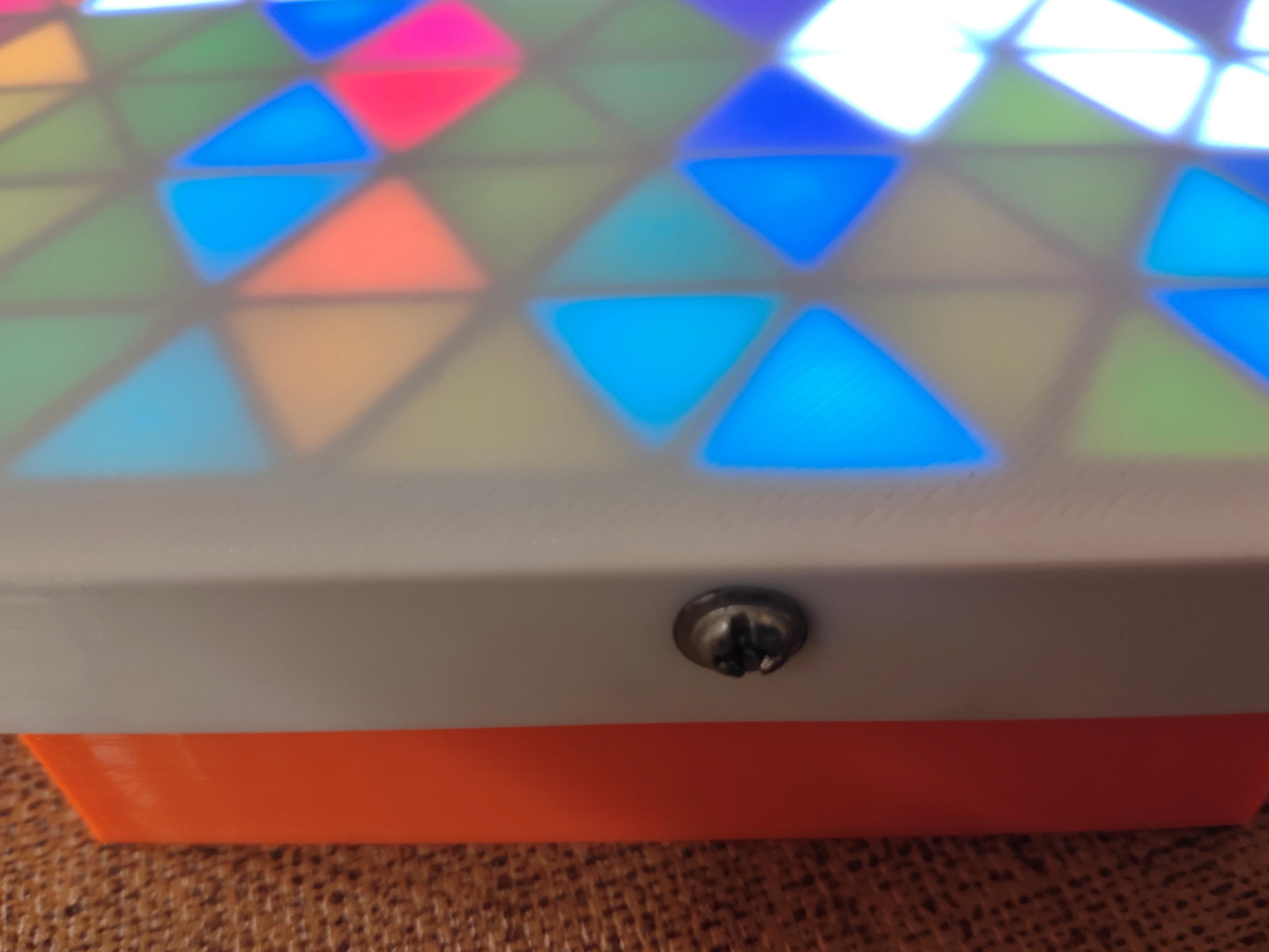
将所有的部件都放入外壳里面。通过在外壳侧面开孔,拧上螺丝来固定即可。


