
详细说明

该项目通过 Arduino 和四块点阵屏,实现32分频的音频(音乐)频谱可视化显示。
这里用了大量篇幅对其原理做了解释(初学者理解起来开可能稍有难度),并且提供了完整的原理图和源代码。如果你喜欢直观地观赏音乐随着声音跳舞的话,可以一试!
往期精彩内容还有《用 Arduino DIY 假唱机器人+卖萌表情包》。
链接表
文件库
source_code.ino
[6453 Bytes at 2019-02-21, 175 次下载]
教程
组件清单
- Arduino Nano R3 × 1
- 电阻10k欧 × 1
- 电阻4.75k欧 × 3
- 电容100nF × 2
- 电阻100K欧 × 2
- 轻触开关12mm × 1
- LED显示器32X8 × 1
- 5V电源(用于USB供电) × 1
材料清单
Arduino Nano R3 × 1
电阻10k欧 × 1
电阻4.75k欧 × 3
电容100nF × 2
电阻100K欧 × 2
轻触开关12mm × 1
LED显示器32X8 × 1
5V电源(用于USB供电) × 1
主要特点
1、使用易于安装的库 arduinoFFT 和 MD_MAX72xx。
2、支持五种不同的显示模式,可通过按钮切换。
3、音频信号的左右声道都是混合的,不会错过任何节拍。
4、原型使用 32x8 LED 点阵,你可以随意改变。
5、音频可以从耳机输入或播放设备的Line-Out输入。
项目流程图

原理图
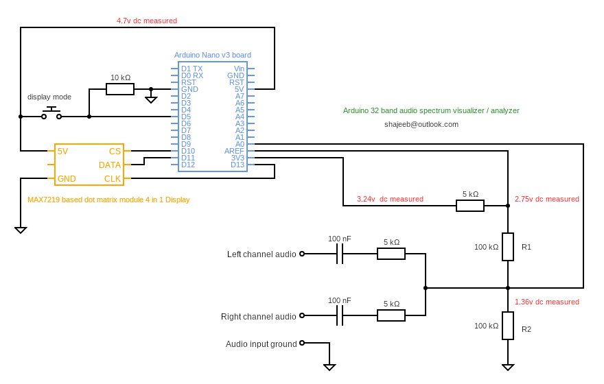
系统原理描述
Arduino 板(ATmega328P)内置模数转换器(ADC),可以将输入音频信号转换为数字样本。 ADC 设置为采样时钟频率为 38.46khz 的输入信号。这是通过将 ADC 预分频器配置为32分频来实现的。采样频率为 38.64Khz 这就意味着数字样本可以高达19.32Kz(奈奎斯特定理)的输入频率,对于音频信号来说非常好的。
为了显示音频信号的频谱,左右声道混合在一起并反馈到 ADC 的 A0 模拟输入。你可以使用一分多的音频线将信号同时馈送到频谱分析仪和另一个放大器上(如果有必要的)。
ADC 设置为使用外部参考电压。在这个项目中,参考电压来自 Arduino 板上的 3.3v 稳压电源。当模拟信号在零电压附近震荡时,我们需要在 ADC 的模拟输入端配置一个直流偏置。这可以确保 ADC 输出不会截断输入信号的负周期。相同的 3.3v 稳定电压由两个电阻 R1 和 R2 分压,然后反馈到模拟输入以进行直流偏置。使用此直流偏置,即使输入信号断开,ADC 也会在输出中产生 512 。稍后在代码中这个 512 将由 DC 偏置抹掉,从而读数代表实际的输入信号的变化。
ArduinoFFT 库是将输入模拟信号转换为频谱的核心代码。这个库易于使用,而且输出非常的准确。 原型配置为生成 64 个样本,并使用这些样本进行 FFT 。 ArduinoFFT 库可以对 16 到 128 之间的样本进行 FFT ,在程序中进行配置。但arduinoFFT库对 128 个样本的计算速度慢,因此我坚持最高值为 64 个,这样效果最好。
本项目使用的显示为32列×8行 LED 矩阵。 MD_MAX72xx 库使显示控制部件非常容易。该库提供打开/关闭该程序中正在使用的任意数量的 LED 功能。每个频带的幅度被映射在 0 到 8 之间,这取决于每个列中的 LED 接通的数量。
该程序提供五种显示模式,你可以轻松修改或创建不同的模式。这个项目中使用按钮来切换模式。
频率响应
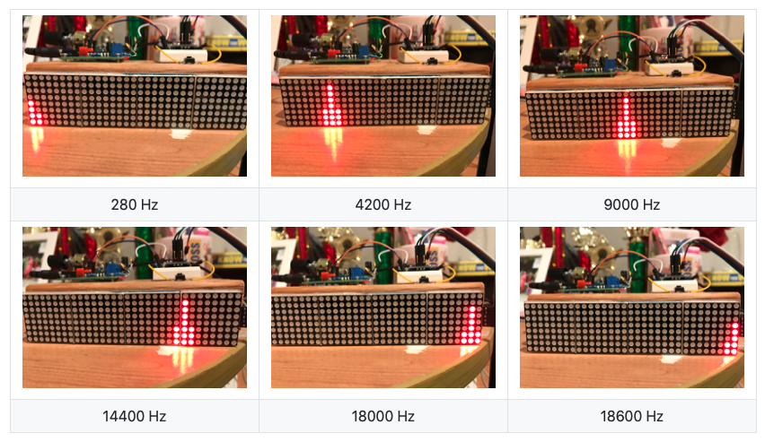
实验证明,系统能够响应高达18.6Khz 的频率。
有关此项目的更多信息,请访问我的 GitHub :https://github.com/shajeebtm/Arduino-audio-spectrum-visualizer-analyzer/
连接输入
你可以通过多种方式将音频输入到频谱显示仪。你可以从音乐播放器/功放的 Line-Out 输入。 其他选项是从手机/音乐系统的耳机输出获取音频。 我不建议使用另一个麦克风接收音频,因为信号水平和频率响应将包含许多的因素。
以下是将音乐播放器/功放连接到频谱显示仪的示例图。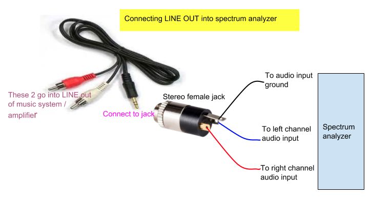
以下是将手机的耳机输出连接到频谱显示仪的示例图。 
将电缆连接到耳机输出时,手机/音乐系统不会出声。 如果你想听到音频并可显示,你必须分离音频并使用另一个功放。
代码
/*
Copyright (c) 2019 Shajeeb TM

Permission is hereby granted, free of charge, to any person obtaining a copy
of this software and associated documentation files (the "Software"), to deal
in the Software without restriction, including without limitation the rights
to use, copy, modify, merge, publish, distribute, sublicense, and/or sell
copies of the Software, and to permit persons to whom the Software is
furnished to do so, subject to the following conditions:
The above copyright notice and this permission notice shall be included in all
copies or substantial portions of the Software.
THE SOFTWARE IS PROVIDED "AS IS", WITHOUT WARRANTY OF ANY KIND, EXPRESS OR
IMPLIED, INCLUDING BUT NOT LIMITED TO THE WARRANTIES OF MERCHANTABILITY,
FITNESS FOR A PARTICULAR PURPOSE AND NONINFRINGEMENT. IN NO EVENT SHALL THE
AUTHORS OR COPYRIGHT HOLDERS BE LIABLE FOR ANY CLAIM, DAMAGES OR OTHER
LIABILITY, WHETHER IN AN ACTION OF CONTRACT, TORT OR OTHERWISE, ARISING FROM,
OUT OF OR IN CONNECTION WITH THE SOFTWARE OR THE USE OR OTHER DEALINGS IN THE
SOFTWARE.
*/

#include <arduinoFFT.h>
#include <MD_MAX72xx.h>
#include <SPI.h>

#define SAMPLES 64            //Must be a power of 2
#define HARDWARE_TYPE MD_MAX72XX::FC16_HW   // Set display type  so that  MD_MAX72xx library treets it properly
#define MAX_DEVICES  4   // Total number display modules
#define CLK_PIN   13  // Clock pin to communicate with display
#define DATA_PIN  11  // Data pin to communicate with display
#define CS_PIN    10  // Control pin to communicate with display
#define  xres 32      // Total number of  columns in the display, must be <= SAMPLES/2
#define  yres 8       // Total number of  rows in the display


int MY_ARRAY[]={0, 128, 192, 224, 240, 248, 252, 254, 255}; // default = standard pattern
int MY_MODE_1[]={0, 128, 192, 224, 240, 248, 252, 254, 255}; // standard pattern
int MY_MODE_2[]={0, 128, 64, 32, 16, 8, 4, 2, 1}; // only peak pattern
int MY_MODE_3[]={0, 128, 192, 160, 144, 136, 132, 130, 129}; // only peak +  bottom point
int MY_MODE_4[]={0, 128, 192, 160, 208, 232, 244, 250, 253}; // one gap in the top , 3rd light onwards
int MY_MODE_5[]={0, 1, 3, 7, 15, 31, 63, 127, 255}; // standard pattern, mirrored vertically


double vReal[SAMPLES];
double vImag[SAMPLES];
char data_avgs[xres];

int yvalue;
int displaycolumn , displayvalue;
int peaks[xres];
const int buttonPin = 5;    // the number of the pushbutton pin
int state = HIGH;             // the current reading from the input pin
int previousState = LOW;   // the previous reading from the input pin
int displaymode = 1;
unsigned long lastDebounceTime = 0;  // the last time the output pin was toggled
unsigned long debounceDelay = 50;    // the debounce time; increase if the output flickers


MD_MAX72XX mx = MD_MAX72XX(HARDWARE_TYPE, CS_PIN, MAX_DEVICES);   // display object
arduinoFFT FFT = arduinoFFT();                                    // FFT object


void setup() {

    ADCSRA = 0b11100101;      // set ADC to free running mode and set pre-scalar to 32 (0xe5)
    ADMUX = 0b00000000;       // use pin A0 and external voltage reference
    pinMode(buttonPin, INPUT);
    mx.begin();           // initialize display
    delay(50);            // wait to get reference voltage stabilized
}

void loop() {
   // ++ Sampling
   for(int i=0; i<SAMPLES; i++)
    {
      while(!(ADCSRA & 0x10));        // wait for ADC to complete current conversion ie ADIF bit set
      ADCSRA = 0b11110101 ;               // clear ADIF bit so that ADC can do next operation (0xf5)
      int value = ADC - 512 ;                 // Read from ADC and subtract DC offset caused value
      vReal[i]= value/8;                      // Copy to bins after compressing
      vImag[i] = 0;
    }
    // -- Sampling


    // ++ FFT
    FFT.Windowing(vReal, SAMPLES, FFT_WIN_TYP_HAMMING, FFT_FORWARD);
    FFT.Compute(vReal, vImag, SAMPLES, FFT_FORWARD);
    FFT.ComplexToMagnitude(vReal, vImag, SAMPLES);
    // -- FFT


    // ++ re-arrange FFT result to match with no. of columns on display ( xres )
    int step = (SAMPLES/2)/xres;
    int c=0;
    for(int i=0; i<(SAMPLES/2); i+=step)
    {
      data_avgs[c] = 0;
      for (int k=0 ; k< step ; k++) {
          data_avgs[c] = data_avgs[c] + vReal[i+k];
      }
      data_avgs[c] = data_avgs[c]/step;
      c++;
    }
    // -- re-arrange FFT result to match with no. of columns on display ( xres )


    // ++ send to display according measured value
    for(int i=0; i<xres; i++)
    {
      data_avgs[i] = constrain(data_avgs[i],0,80);            // set max & min values for buckets
      data_avgs[i] = map(data_avgs[i], 0, 80, 0, yres);        // remap averaged values to yres
      yvalue=data_avgs[i];

      peaks[i] = peaks[i]-1;    // decay by one light
      if (yvalue > peaks[i])
          peaks[i] = yvalue ;
      yvalue = peaks[i];
      displayvalue=MY_ARRAY[yvalue];
      displaycolumn=31-i;
      mx.setColumn(displaycolumn, displayvalue);              // for left to right
     }
     // -- send to display according measured value

    displayModeChange ();         // check if button pressed to change display mode
}

void displayModeChange() {
  int reading = digitalRead(buttonPin);
  if (reading == HIGH && previousState == LOW && millis() - lastDebounceTime > debounceDelay) // works only when pressed

  {

   switch (displaymode) {
    case 1:    //       move from mode 1 to 2
      displaymode = 2;
      for (int i=0 ; i<=8 ; i++ ) {
        MY_ARRAY[i]=MY_MODE_2[i];
      }
      break;
    case 2:    //       move from mode 2 to 3
      displaymode = 3;
      for (int i=0 ; i<=8 ; i++ ) {
        MY_ARRAY[i]=MY_MODE_3[i];
      }
      break;
    case 3:    //     move from mode 3 to 4
      displaymode = 4;
      for (int i=0 ; i<=8 ; i++ ) {
        MY_ARRAY[i]=MY_MODE_4[i];
      }
      break;
    case 4:    //     move from mode 4 to 5
      displaymode = 5;
      for (int i=0 ; i<=8 ; i++ ) {
        MY_ARRAY[i]=MY_MODE_5[i];
      }
      break;
    case 5:    //      move from mode 5 to 1
      displaymode = 1;
      for (int i=0 ; i<=8 ; i++ ) {
        MY_ARRAY[i]=MY_MODE_1[i];
      }
      break;
  }

    lastDebounceTime = millis();
  }
  previousState = reading;
}代码也可在项目文件库中自行下载。
https://make.quwj.com/project/101