


Hardware components | ||||||
_ztBMuBhMHo.jpg?auto=compress%2Cformat&w=48&h=48&fit=fill&bg=ffffff) |
| × | 1 | |||
 |
| × | 1 | |||
 |
| × | 3 | |||
 |
| × | 1 | |||
| × | 1 | ||||
| × | 1 | ||||
Software apps and online services | ||||||
| ||||||
| ||||||
 |
| |||||
Hand tools and fabrication machines | ||||||
 |
| |||||
 |
| |||||
 |
| |||||
I've always wanted to automatically detune and retune the strings of a guitar while the guitarist was playing. In this project I tried, and managed, to do exactly that 😛 with the help of technician Johan Nördstrom. After completing the project I wrote some music for guitarist Ruben Mattia Santorsa.
Check the track on Spotify.
Also, check this video with Bertrand Chavarria-Aldrete improvising while the motors are modifying the tuning:
https://www.instagram.com/tv/CFRdw-bg9xS/?utm_source=ig_web_copy_link
Attempt 1The first attempt was on a classical guitar. Johan and me tried to build a system with two linear motors that would move a second, mobile bridge up and down, in fact modifying the length of the strings. It didn't work as planned, since the noise of the motors was overwhelming, killing the feeble sound of the guitar.
Attempt 2Johan found out about the Tronicaltune system, a set of motorized tuning pegs for electric guitar that are meant to automatically tune the guitar at your command. The original Tronicaltune system is constituted by six machine heads and a shaft that is attached to the headstock, containing a circuit with a pickup for each string. While strumming, the circuit would compare the sensed pitch to the desired pitch, and adjust the tuning by controlling the motors accordingly.
We found and bought a heavily discounted Tronicaltune set, and tried to insert its motorized pegs into the classical guitar, discarding the original circuit and hacking the machine heads. In order to hold the machine heads in place, I designed and 3D-printed a special piece which you might still find useful: you can download it from Thingiverse. Still, the wood of the guitar was amplifying the noise from the stepper motor big time!
Attempt 3 and final setupThe final resolution was to buy an electric guitar. The body of an electric guitar is not made for mechanically amplifying the sound; there is no sound hole. I bought a Fender Squier from Thomann (full model name: Fender Squier Affinity Strat HSS IL SS).
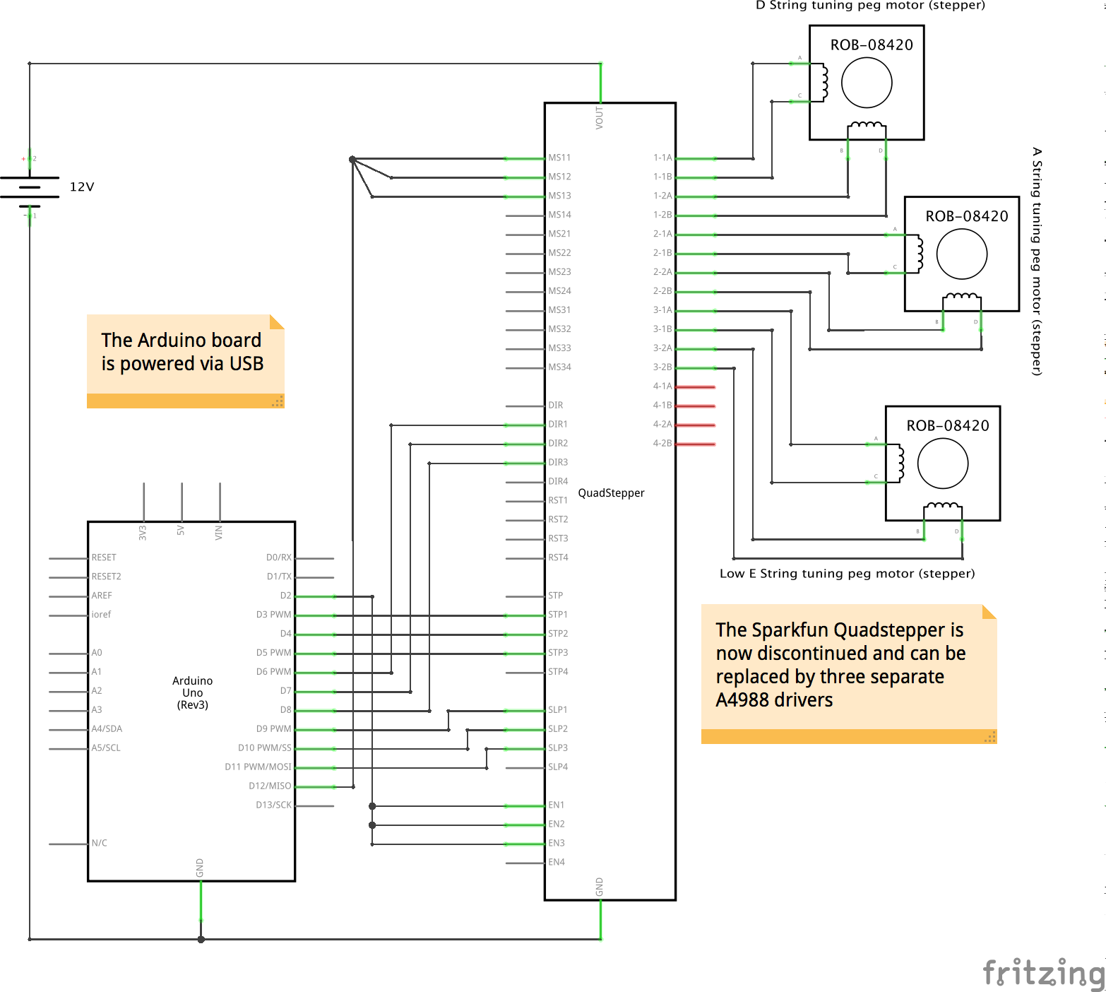
The most delicate process was to open the Tronicaltune machine heads. After a test wiring, Johan got rid of the mechanical contact parts (including springs) and soldered very thin wires to the four terminals of each stepper motor. The four wires needed to be connected to the four outputs of each A4988 driver board.
The easiest part was to connect the Arduino to the A4988s. See the schematic for checking how I decided to hook up the wires. We also made some tests and verified that the stepper motors were working at 12V.
Mounting the motorized tuning pegs on the Fender didn't require the 3Dprinted holder, but needed some extra sorcery on the guitar. I actually used some Prusament cylinders from the previously 3Dprinted holder in order to safely rest the pegs in the peg holes of the guitar..
SoftwareAll the software I wrote was meant to make a DAW (I used Reaper), providing MIDI signal, able to control the motors in real time. Reaper was outputting MIDI notes to a Max MIDI port. Max was listening to that port and converting the MIDI notes to numbers, which were sent via Serial to the Arduino. Finally, the software in the micro-controller would convert these numbers into digitalWrite commands for the motors.
Let's see how these three steps actually work.
Reaper sending MIDI notesA piano-roll of the MIDI item shows us MIDI notes. I decided that any note equal or above pitch 64 (E4) would make a motor turn so that the corresponding string would tighten up (glissando upwards). Any note below 64 would make the string more loose (glissando downwards).
For each motor I choose a different MIDI channel (chosen based on the colors Reaper had to offer for those channels 😃): channel 8 for string 4, channel 12 for string 5, channel 12 for string 16 (yes, I motorized only three strings).
On top of this, there is a global control for motor speed, which I never used when I wrote the music for this special guitar, but still present in the software. This was sent as Controller 1 (any channel, 0 = incredibly slow; 127 = maximum speed).
Reaper was also playing back a scrolling video-score for the guitarist to read, so that the playing and the motor control would always be perfectly synced.
Max parsing MIDI events and sending them to the ArduinoThe Max patch I wrote had the main function of parsing the MIDI events received from the DAW (but actually you could even connect a MIDI keyboard and control the motors live, for example, or use Max itself). Max was first routing MIDI note messages as per channel (8, 12, 16 for the guitar strings 4, 5 and 6). Then it was checking the pitch and velocity of the note event. MIDI pitch bigger/equal or smaller than 64 was critical to understand if the motor needed to move in one sense or another (direction), MIDI velocity was used to understand if the motor needed to move at all (velocity bigger than 0, which means "note on") or to stop (velocity = 0, or "note off"). Basically, Max was handling seven numbers, sent as bytes via serial to Arduino (with two bytes of value 255 and 250 before and after in order to be sure to distinguish the start and the end of the byte list (is it technically called array? 😨):
- Channel 8, velocity of the note, to start/stop the motor for string 4 (Arduino sketch:
byte m1on) - Channel 8, pitch, for the direction of string 4 (Arduino sketch:
byte m1sp) - Channel 12, velocity of the note, to start/stop the motor for string 5 (Arduino sketch:
byte m1on) - Channel 12, pitch, for the direction of string 5 (Arduino sketch:
byte m2sp) - Channel 16, velocity of the note, to start/stop the motor for string 6 (Arduino sketch:
byte m3on) - Channel 16, pitch, for the direction of string 6 (Arduino sketch:
byte m3sp) - Controller 1, any channel, for the speed of all motors (Arduino sketch:
byte globalSpeed).
Another useful Max patch function is that of assisted tuning: by clicking the UP and DOWN buttons for each string, you can retune the guitar as you like, without the need of turning the pegs with your hands. A monitor section was showing the pitch currently played, for the performer to see if the string needed to be tuned up or down, as in a common tuner.
Copy and paste the following code in a new Max patch, and the patch will magically appear:
<pre><code>
----------begin_max5_patcher----------
3718.3oc6crsaiab8YueEDB4Qsxy8KaeJooX6h1jFjsoo.IEKnEosYBEo.E0
dKH4auCmgRhxZH4HqgTV6Fa.IQJJdlyk4baNmg+1ytZxM4uOd0jfWD7SAWc0
u8rqtReppSbU8wWMYQ36mmFtReYSlmuXQbV4joluqL98k5y+Mu5qe0ymmmUV
jmlFGEDmFOurHYdvcqSJCKBJWmkjcWvx36VE71jvfurHZcRV9l6SZRV7770Y
5aFp9jKKhWofUXYRd1aJT2Oy.ExmAlFPmwAbAkRADpfCIjoALIn5av3Yff+W
88HIRO7xu4WdNEuAZ2pFmqR9XrFXD0uwb5r0KRxRiK0XJzxfn44UWb95xMWM
nwcNKbg9NO4KKRBSC9p7znM.dYX476UzgFXCRHlgnpAOXeDhJlFPvUCtpuRg
PU2ge+YOq5koNxrVDuZU3cwGvrturb4Kt9528t2MKLs5ZxhJxWFWjjkLSwfm
zM8mPvZxrr5UDfpeqIMuBNyySyKLWuZzCoLACwITfT.TbJMeRgvMOMVNM.1B
mCYiyAQ14bnihyAsw49mqmmDEF7xBEkItClGaCySfaiXX.U4GVFa9ISlr8qt
qHLJI1HyuASt4t8nbBl5O9zV9zNnbyc2ljlp+ouYCr1c+sbQ5WgmBXzuh1xh
UbQn9hQlOAqnDvt9sa9onoMdAZ85CWWluG0ZFW5w4C+ketPccAogqyle+ME4
uaUbQvW.6T4TSwSgMwSY2Rm2mDEEerxk+m3hnvrvNkHkZIRNUKQBgZMHXPOR
jOBhYaVBdYZ9MJ0dudYbbTOZRvB3L0XkH0uAAHyjH6JAH7ImS8zXLyLV0CRL
BrarddHdHIsZ.gPlYZcS7vxIOELxUOJGJp22jmkTluwYiWzmzmTOEgSmAgRo
fJALFQMRqTdIMSaZwdDla0SB3LNhhfHLGodmInmU4UngjKs4WgftC87I8W4u
Wd1yyu8Vqj9iwIOJjYTbokTnxtbrC4SgaajRifBkpc7DROMg23OFFM+Ol3F5
qT5HD..j.jXLkCT9HQz7tpWsQKfLOPKPsSKnb8LXlbyf3ACkCLtrJ4trvzIS
29I+JwoB6HXYhZX9BeIxgL5n5QjiNvhbbgdPPP9PjqM+d9BnRiLXhEzytTDp
SOUrfFBrY5KfrSbAg7uuHYwuSMrO.+p39JeEsgfXqHH9XmNHHZuBnXsFBBzA
DTMS3lvr6djH5pzjn3hIachzHYOoWScLiSBBK15.3YLo5egxLAChQUmDwwy3
L.PcffohtVYSyp1F9NKPEJySkwEuINK7lz3lx2mPzYntlhnI1DwLpBk3DH.p
PBrTM5U9nIEJibf5+phGAoj9HJUoHpPpDKwTJpclTEYcp4scn8cY4JnmlL+W
0iWOpE6u+wW3l8.nNaE05lZ0WOw.qahYLGh7h4vaSyUP1QzmTGTCqSuyXtHT
tmmaftyAzs4p3C0CElujd2n3fo0yKjGfPco3XGvhhmmrHLcYZ3bSd7f9S64h
x7asn5DS5T7xcaCHssMhgBfQirsgUwoAOWI7Zy7GFeDl+5fIyM5nHFelnh9Q
QMCdpuQ0pnISSVzhwdLzOF6UFPLFA0uYNXHXnGiFCjIKkVle0j..t.TXTSco
l.hdRpv35eXUbwpq+uIYIW+5OjM+Ge02csxaZva9aouTuJ.uYQtJ77UWqhDX
w5rn+X1h2ma7d20TsAEGgxmtnlRiVGhIySByQcFHiRrKrz6yMqhEL.ZyCU+n
kkCLYlV3rG3mRXZs4GddXTULHJ+W3VPUneP0MwmalnTmQdz3k3yuOddbxaii
BhBKC6ygbs1IhJtHZuYaBBAW.oaRImYx673kto+5844qhC9gW+UAKyKJ8PB.
L1oMdzVErj9nV3J.4SetRmKt3PkDvvr0pQV8ZAGnhgJt3Vk0l9RmsYVK7vk0
ESDcN8.Ht.XDbyzCxHN83q+W+321CQu1vGhqI9RSXkj1nyLqqBqXvV+7u4CJ
RaTv2Uj2D29k0qJStMY9A2QKjcBhpI6HyBoaAAq.nV5rwM5AqAqThZt90S0m
ho3hDLTIbQIxpSA0eB.q+F8xay8J+7G9t93ll0lBJzFWLGzN2jeAxMMqsYcJ
GrffWPbSWlcV66layNIWb7SLA74zrS.+HlcRu.4ljOulcdLlNwWbrSD8yISm
niwxI5BjYdAZ4rsUsDB.sjISozOYxDy3Fu0qWE1AK2zsghXP.1FB1.sOMLDI
Ey353Q3MpkyQDC6fIx8LSjvdZwDkBOwCEHCOzXI5IEOj4YdHj9DiGR8DOT49
fB+vlzyN9rPq3F1S3lobHpSeiJ1M5vfaquYcYoxDXe4WxrfPlkPlY7Uk2RNk
DxittFNN67jNhxkXRUDxDufsQZqKa31kO7gEuPQ95rnXMBh2s1U2GlEUUrd5
JHYvn7PSEp5FkWBNeTdLU7oEkGeDh7R34ivuI6nexP3qU1.MEpSeJaDmekMP
D9SJkMtQ44hyuxlOYn73iPjGgN+Jat.H7skNiW+u+9W8suLfDr4u5SPCBd3o
XMN0O2qZKybGCgotIMvsjFDNZxSgETSvOXr9HHz6WUssVDslXloDRMvpZuh1
jvICrDdWqShTpGnBSmxZYf5IOuchrg3Z36FUCbFoZXcnXOMHZPNRKd6DUCdF
oZX0fB8jgrwp6ZBZ+DM5YjlYxiwfSxTCna5WqFrYzYzCqZyC6l6oMdoEpKaf
otndKCr50sfBNpVxnkLe2Hg1PrtmnkbFgCnBARwMk5VZeu7dCI0zF+UEcKKR
14KPyFi8XJUvNpqeldVifidX8X6OTP4lTYr0xcDi7SIWWO2hY36lT+1O22qU
63GSCJheqsR5T3IbzjQMFTW7p08Ay3hiKCm+q1vPek6dCFR4xMt0MxY1dGhz
QGUUkXZFrEsLMoJcWf8dweucs7OELxcRw7xzjLaKVk7HzKg6pQuzRAa5wNGP
uFsu01.07or+uVs53Af89GQskKcg8IDxikECIPiK8TSAqObsRYawbt.tMNxF
eTc.pkOiadQ3eNKOa2wQIEM91leSWek96beGC5XJ8255wttRLQctOBInm0He
glcs.A9fgpGU.xYts6S3j9OAdX0+gTtrn0+IGV8e8tHZsQqT9V6LshLvzJD3
rRqXhdKhUn6DqA1vJTEO4SYAKHV5NsBMvzJH6rRq38IXI3lpkvIhEXXIVLhd
r7jUvBScmVwkCrfEZbnUs43SYdfosECp1EABByhBvV7ziC7ST3PSFsYXs80S
s65awE10YsD.Gi3m9qr1LCSV2.zGkO6iClh8TmjZTqvDnmrXJxSXJBaPUSKH
eFQ0VyvBC5mLrTuOkwL6miCaFVZUGcvNSZMQQeUAnl08jgzt3L5aMOlLAJTZ
2C1skU0L871UDQN1U6cCmznNkKcjSNcH3nLQ.Pgvt1q6DOUmnFwWJmsK8Ic2
o6dOSglTjXK00jiXaXB1KWtd2TABHirzbVdYr0bfQ.9IGXaPPSNvbBA8TRvZ
sFDhSm8Oh+vM4gEQ1PboebGBS4FGIfC4Fg1s8sahHLNBa1MUsTJqMS6IZnif
moMCinCaY01FspuF4lRXlkt1IhEcfCdv3M84hVEMwscb.WHUhAlRQ3mUwp4t
MEjTyP6jTMv4PqdmgXnoTcrYpXpCsCWDUpe1IULEcREZZ16HbaaqxqhCssX2
PhebJpFEofgcAFaco7iWFmEs21VRSjD6G9nwyOtYACF8dK4FGMT3zTZ3.mpW
dcqneLyosrM92RqSpqVFkyap+z8HotKJe31i+9an9HcsjTc03sOzDvUmB191
p+iXm+2oQVaa5+Olw39a8+OhafRUioLhLsdsKOr.rcUKKxql8UKun.qOefBD
5lcemj7G3zqV2iHmGaYqh0q34MUM.m88lPqsZcOOxVrmlmCWo0tVjUD1ryb0
V282V3VSr1Q0fGAIaYXVbZe4omq4XlJ2BYdCiayqnsDyaxKhhK1alX8ifkMc
3sVqvdObVzOfNv6+29SRGlcaVpIiEDyNdHDI191V.uHOZu9V2pFhJMBa05wZ
fp0O2RN3YQiBaIPXix7aers59sUQH9f1fuIkCR0zS7tqvn0q4s6gpinCjDCD
rSfop6Z6TfgdIJvXvv58Bv+TbwGhKXiBPByXqfIevCk.qBOrKQgGiZebcuL8
mROmlzS09mgfuS.Bpz6vztY6jHztJp6RRDh.LOWdjhOakgzWjd8MdvyVPM4p
576KXsJecw7MNRs4A9VvNXEEupLIaKK4m18X2pwE03ApkUwYWgc0lHSuvtZc
xCZKGzNCIgKPB6CHwGMHwbARHe.I5nAIrCPppRea7zqSqvROkdj.M9PPCGIP
SODzfSCzv8nk1A8F9+oCo9PRoWlX.bAmD9BRiCN4.ff9.PB4XgRZH0GaRuoG
c5fR3hDgzWPZbHetXngru0cOouxIPisC4SSckXrlFvcRhg6KHMJRLa7j5QYl
Ac5fF5BnY9VX0MrlX2kB3Hf0X6fFL7XMBLDyQYmOGoXXWEyHmGrFMDdt5FVC
GDIbWvZ3vHlgNgPEfmNncRLCMHXcufFLXXceDbtbPjvcJIEChTlKQsP8QJJX
tJNyOQ.oGsnwHqKTWr+4kbgPIGQFJ7qDhafdPlQRbBzvg.qcBzDwff0tDzMw
GxuDWRj.oVH+zgDxEHgNUHMVQPgcIogPevlvN4qKyGPxEOsdvvwSS3bCzfgH
bem.MjaGzmlgeL5HrJ5Yr1EPifCQvaXWb5.6iIoHWR9.1GY1G4RNiP9HorHW
7jB4EpmKQ+f8ghGjKt8K8FjFkzQgbQJG4CCDtfRPeH5AcI44HtufDzEHcptl
.cREAzG3Dcr7MARbOA1mFfviEfPiFsCNZPB.Fq5CvEb5PsqlhuHb4x2FWrp9
h0fXxhvewT+Lho5CSxLGpKCkIEwuMYy0qan1IgEyuOoLdd45BSUy995sG.cA
rTjsNo1gFExo.ot1fppv1UKqK6UcID8re+Y+e9W7hwB
-----------end_max5_patcher-----------
</code></pre>The Arduino sketch (you find the whole sketch in the attachment section) is taking care of receiving the previously mentioned bytes and transform them into commands for the three motors. A serial connection is established
Serial.begin(38400);and bytes are received:
while (Serial.available() > 0 && newData == false) {
rc = Serial.read();
Then, bytes are parsed so that we end up with 7 numbers indicating the commands. Every time the 7 bytes are collected, they are shown in the serial window, just for debugging:
void showNewData() {
if (newData == true) {
m1on = (byte)receivedChars[0];
m1sp = (byte)receivedChars[1];
m2on = (byte)receivedChars[2];
m2sp = (byte)receivedChars[3];
m3on = (byte)receivedChars[4];
m3sp = (byte)receivedChars[5];
globalSpeed = (byte)receivedChars[6];
Serial.print(" m1on ");
Serial.print(m1on);
Serial.print("\t");
Serial.print(" m1sp ");
Serial.print(m1sp);
Serial.print("\t");
Serial.print(" m2on ");
Serial.print(m2on);
Serial.print("\t");
Serial.print(" m2sp ");
Serial.print(m2sp);
Serial.print("\t");
Serial.print(" m3on ");
Serial.print(m3on);
Serial.print("\t");
Serial.print(" m3sp ");
Serial.print(m3sp);
Serial.print("\t");
Serial.print(" globalSpeed ");
Serial.println(globalSpeed);
newData = false;
}
}
The raw commands are converted into motor commands sent to the respective pins.
/// CHECK IF STEPPING ///
if (m1on == 0) {
digitalWrite(step1, LOW);
digitalWrite(slp1, LOW);
}  else  {
digitalWrite(step1, HIGH);
digitalWrite(slp1, HIGH);
}
if (m2on == 0) {
digitalWrite(step2, LOW);
digitalWrite(slp2, LOW);
}  else  {
digitalWrite(step2, HIGH);
digitalWrite(slp2, HIGH);
}
if (m3on == 0) {
digitalWrite(step3, LOW);
digitalWrite(slp3, LOW);
}  else  {
digitalWrite(step3, HIGH);
digitalWrite(slp3, HIGH);
}
This part above checks for each note velocity if it's equal to 0. If it is, the motor is stopped and the A4988 is put into sleep mode (very important for avoiding overheating!). If not, the motor is started.
The next part checks the pitch of the note events against the value 64, and decides the direction of rotation:
/// DIR ///
if (m1sp >= 64) {
digitalWrite(dir1, HIGH);
}
else {
digitalWrite(dir1, LOW);
}
if (m2sp >= 64) {
digitalWrite(dir2, HIGH);
}
else {
digitalWrite(dir2, LOW);
}
if (m3sp >= 64) {
digitalWrite(dir3, HIGH);
}
else {
digitalWrite(dir3, LOW);
}
A further section examines the controller value and scales it to obtain the interval, in microseconds, between each step. And then uses that value as a pause between the steps:
int scaledSpeed = (lowestMd + 127 * 25) - globalSpeed * 25;
delayMicroseconds(scaledSpeed);
digitalWrite(step1, LOW);
digitalWrite(step2, LOW);
digitalWrite(step3, LOW);
delayMicroseconds(scaledSpeed);
If you look at the void loop() section, you can see that the actual operation routine is:
void loop() {
recvWithStartEndMarkers();
writeToMotors();
showNewData();
}
Which means: receive the bytes, write the commands to the motor pins (after having interpreted the bytes), step the desired motors, wait for an interval of microseconds calculated as scaleSpeed, put all three motors to sleep, show the values in the serial window, repeat the loop.
- Don't gamble with the MIDI commands: you will break the strings if you stretch the strings too much. Always keep the circuit powered through a power strip with a button, in case you lose control of a motor (this happened to me, for example, when I connected a USB device to the computer, and the USB ports changed just after a note-on event).
- Don't run the motors continuously for a long time, they overheat and this may cause problems to the motors.


_3u05Tpwasz.png?auto=compress%2Cformat&w=40&h=40&fit=fillmax&bg=fff&dpr=2)
Comments