

Introduction: Easy 3D Printed Arduino CNC Drawing Machine
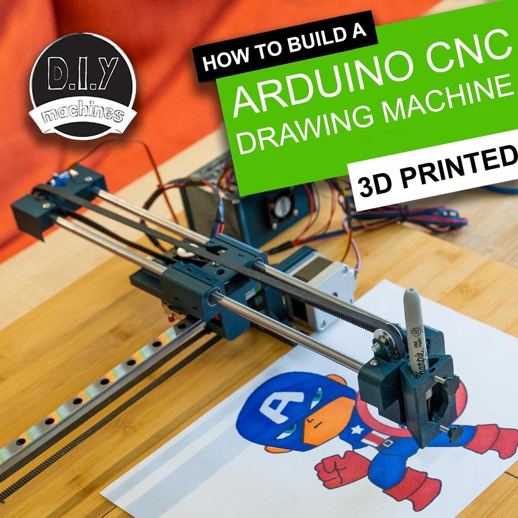


How to make a simple and high quality 3D printable CNC drawing machine to draw on (almost) anything.
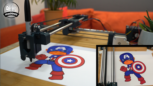
I've always wanted a CNC machine and so has my partner. But they're just too expensive or too large for storing when not in use. So I designed this over a couple of months. Its cost of components is around £75 excluding the old chopping board I mounted mine on. All the software is open source and free. I have used it for drawings, and my partner is using it to draw accurate outlines onto modelling wood to then cut and build his own model boat with.
I'll step you through how to build your own including all the files, code and models you will need to assemble it. Once assembled, I'll then explain how to configure GRBL on the Arduino Uno, create your own GCODE from your drawings in Inkscape and control the machine from Google Chrome using Chillipeppr.
This project has a relatively low cost and can produce some very detailed drawings. I've used it to create t-shirts, cake decorations, drawings to colour in myself (and some it coloured in for me!). You could also use it to draw out scale drawings, wedding invitations, birthday and Christmas cards and anything else you can think of. :)
Feel free to also adapt the design to suite your own needs.
Step 1: Instructional Videos
If you would like to watch some video clips of the CNC machine doing its thing than take a quick look at the intro of the instructional video I made. You can of course watch it all the way through to see how it was built.
There are two videos. The first one covers the 3D printing and assembly of the machine whilst the second video goes over the software side of things. This Instructable covers all the steps laid out in both videos in one write up. So if you prefer written instructions instead then you're in the right place. Read on and I'll break down this entire project for you step-by-step with photo's....
Step 2: Bill of Materials


You will need some components to go along side the 3D printable parts in order to build your own. Here is a list including links to where you can find them on Amazon:
- 8 x15 x 45mm Linear Bearing (x2): https://geni.us/LinearBearing45mm
- 8 x 15 x 25mm Linear Bearing (x1): https://geni.us/LinearBearing25mm
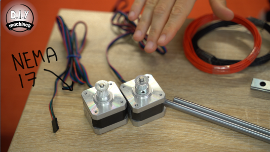
- 12v Nema 17 stepper motors (x2): https://geni.us/StepperMotor
- GT2 Timing belt and pulleys: https://geni.us/TimingBelt5m
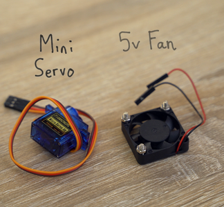
- Micro servo (x1): https://geni.us/MicroServo
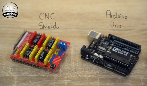
- Elegoo Arduino Uno (x1): https://geni.us/ArduinoUno
- Nuts, bolts and screws (See list below): https://geni.us/NutsAndBolts
- Stepper drivers - TMC2208 (x2): https://geni.us/TMC2208
- Contact switch (x2): https://geni.us/ContactSwitch
- Arduino CNC Shield (x1): https://geni.us/ArduinoCNCShield
- 30mm 5V Fan (x1): https://geni.us/30mm5vFan
- 8mm Chromed Steel Rod (35cm x2 & 5.5cm x1): https://geni.us/8mmChromedSteelRod
- 30cm long linear rail with block (x1): https://geni.us/LinearRail300mm
- Electrical wire: https://geni.us/22AWGWire
- 12v power supply - 2A or greater (x1): https://geni.us/12VPowerSupply2A
- 6mm Idler Wheel - 3mm Bore (1): https://geni.us/6mmIdlerWheel3mmBore
- Wooden panel to mount project at least 36x42cm (I used an Ikea ‘LÄMPLIG’ chopping board)
Nuts, bolts and screws needed:
- M5 x 25mm (x2)
- M3 x 18 (x3)
- M3 x 12 (x2)
- M3 x10 (x3)
- M3 x 6 (X14)
- M3 nuts (x9)
- M5 nut (x1)
- Short wood screws (x8)
You can see all the components listed separately 60 seconds into the video: https://youtu.be/XYqx5wg4oLU?t=60
Step 3: Assembling the X Axis - Fitting Idler


We'll start with the X axis. This is the one which runs from left to right (and back again!). :)
For this you will need the first three of our 3D printed parts. They are:
- BaseEnd-Powered.stl
- BaseEnd-Idle.stl
- RaftMount.stl
All of the 3D printed parts can be found on this projects page at Thingiverse: https://www.thingiverse.com/thing:4537916
I printed all my parts for this project with a 0.15mm layer height and 40% infill for improved strength. I also use a brim to help ensure adhesion to the print bed.
Once printed we can use an M5 x 25mm bolt and M5 nut to add the 5mm toothed idler to the 'BaseEnd-Idle.stl' 3D printed part.
To do this, thread the bolt through the opening from outside the print, through the centre of the idler and secure with the bolt at the other end. This needs to be firm but not so tight so as to deform the print.
Step 4: Assembling the X Axis - Add Linear Rail and Fit to Base Board
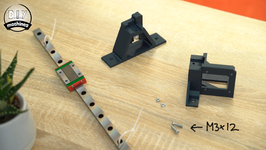


For this step you'll need:
- M3 x 12 bolts (x2)
- M3 nuts (x2)
- The assembly from the previous step
- The 3D printed part 'BaseEnd-Powered.stl'
- The linear rail
- Wood screws
- Base board
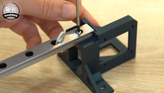
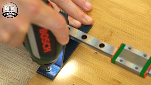
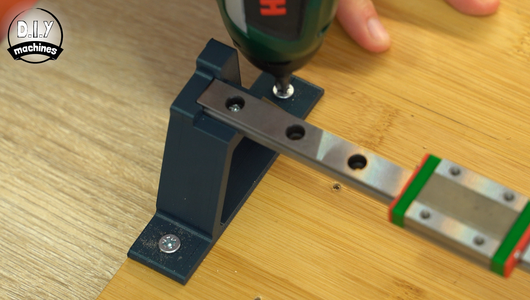
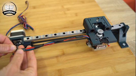
Sit the linear rail between the two 3D printed bases.You'll find a notch in both pieces for it to nestle into. Use the bolts and screws through the holes at both ends to hold it in place.
If there are any cable ties along the rail when it arrived these can now be removed. They are often included when you purchase a rail to prevent the sliding block from travelling off the end of the rod and ball bearings falling out. (This would be a bad thing to happen).
The rail and two attached 3D prints can then be placed onto the base board. The end with our idler wheel should be fitted up to the left side edge of the board with the front of the print at least 28cm from the bottom of the board. Use wood screws to secure it to the board.
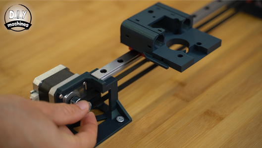
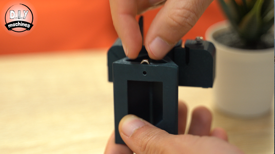
Step 5: Fit the Raft


For this step you will need:
- 3D printed 'RaftMount.stl'
- M3 x 10 bolts (x3)
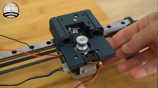
Slide the raft over the metal block on the linear rail and secure it with the bolts through the three holes which I have circled in the above image. They should be done up firmly, but don't over tighten them as you may damage either the printed part or rail block.
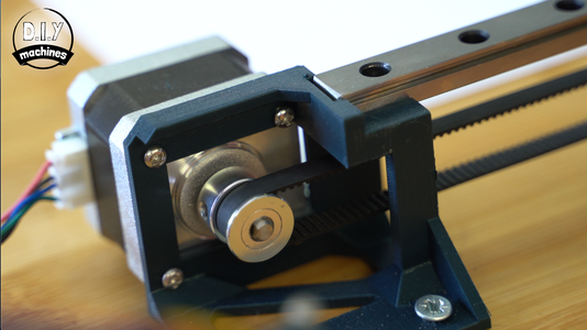
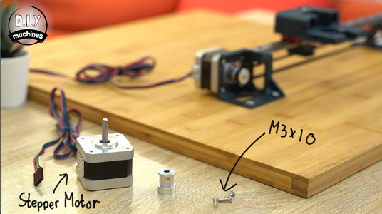
Step 6: Add X Axis Stepper Motor and Timing Belt
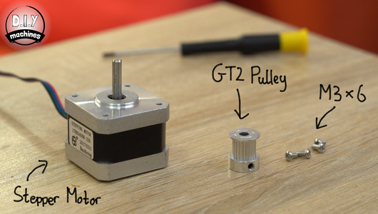


For this step you will need:
- NEMA 17 stepper motor
- GT2 Pulley
- M3 x 6 bolt (x4)
- 80cm length of GT2 timing belt
The motor is positioned on the outside of the 3D printed bracket that we have already fixed to the base board. The stepper should be orientated so that the wires are exiting away from the linear rail. This is to help ensure that the wires from our electronics do not interfere with our projects operation later when we do some drawings. :)
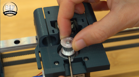
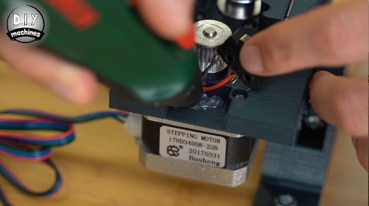
The timing pulley can then be added to the shaft of the stepper motor, but don't tighten the grub screw just yet.
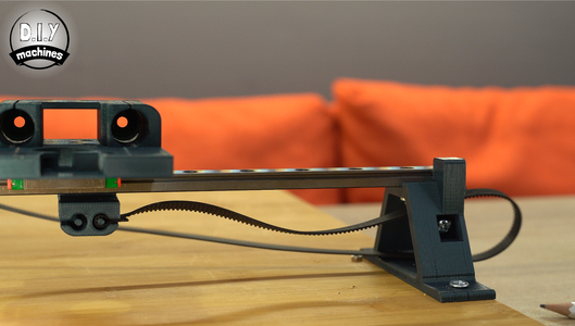
Take the 80cm length of timing belt and curl one end of the belts toothed side back around on itself so that the teeth interlock with each other. This loop can then be inserted into one of the hoops on the underside of the raft by pushing the loop you made just now around the pin. Use a flat headed screwdriver or the tip of a pair of pliers to push the belt further into this recess.
Pass the belt over the idler and then back around underneath it. Keep going towards the toothed pulley we added to the stepper motor. Pass the belt around this pulley and then head back towards the raft. As before form a loop with the end of the belt and fit it to the other side of the raft. This time you will need to keep the belt under tension whilst you insert it.
To test if the belt is at the ideal tension, rotate the stepper pulley back and fourth by hand and check that the raft changes direction without hesitation. If when you change direction there is some slack in the belt which needs taking up before the raft responds then the belt is too loose and you should reseat one side of the belt adding a bit more tension as you do so. If it is too difficult to turn by hand then you might want to try loosening the belt tension slightly.
When you're happy with the tension then you can slide the raft back and fourth a few times by hand before fixing the grub screw on the side of the pulley against the flat side of the stepper motors shaft.
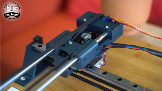
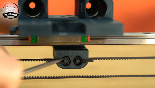
Step 7: Outfitting the Raft - Adding Idler Wheel


For the following steps you'll need:
- Idler Wheel (3mm internal diameter)
- M3 x 8 bolt (x1)
Secure the idler by inserting the bolt through the top hole as shown, through the idler, and then down into the hole below.
This was a quick and easy step. :)
Step 8: Outfitting the Raft - Adding Stepper Motor

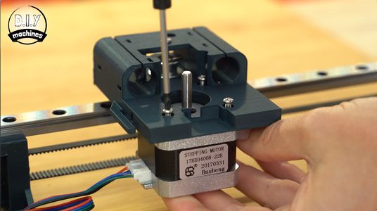
For this step you'll need:
- NEMA 17 stepper motor
- M3 x 10 bolts (x3)
Install the motor from the underside of the raft ensuring that its wires are exiting from the stepper motor towards the small arm on the side of the 3D print. (Later this will be used for cable management). It's secured with three M3 x 10 bolts.
The toothed pulley is then added to the shaft so that it sits flush with the tip of the shaft. Both the grub screws are tightened whist ensuring at least one of them is tightened against the flat side of the shaft.
Step 9: Outfitting the Raft - Fitting Linear Bearings


For this step you will need:
- 45mm linear bearings with 8mm internal diameter (x2)
- Zip ties (x4) optional
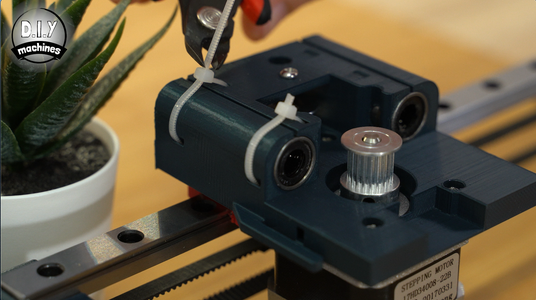
Two two linear bearings are simpler pushed into their respective recesses. Depending on the tolerances of your 3D printed parts it may require some deliberate pressure. If they slide in too easily then they may not stay in place during use. Don't panic - we have a solution for this! :)
There are four sets of slots which allow you to feed a cable tie through the internals of the 3D print and then tighten around the linear belt.
Step 10: Preparing the Contact Switches
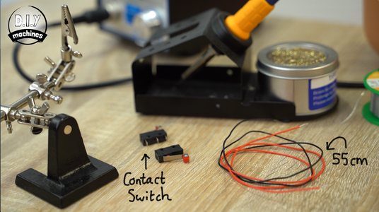


For this step you'll need:
- Some lengths of electrical
- Contact switches (x2)
We need to solder a pair of wires to the Normally Open (NO) and Common (C) terminals of our contact switches.
My switches have these pins already labelled. If yours do not then we can identify a suitable pair of terminals with the help of a multimeter.
To do this set it to continuity test and connect its leads to two of the legs on the contact switch. You should see a change in value (and on most multimeters also hear an audible tone) when you press the contact switch. This means you have a suitable pair of legs to connect your wires too. If not, try another pair of legs.
Solder your 55cm wires to the legs we identified just now and then repeat for the other contact switch, but this time attach a pair of 60cm long wires.
Step 11: Installing Contact Switches

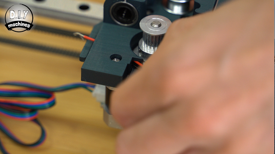

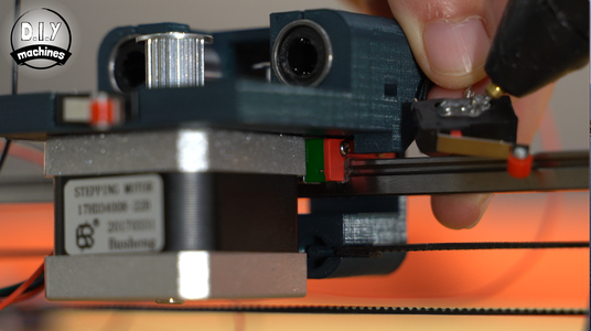


The contact switch with the 55cm long wires should have its wires threaded through the the opening next to the stepper motor. Keep pulling the wires all the way through and then use some hot melt glue (or similar) to glue the contact switch into its recess.
Ensure that the hot glue does not interfere with the operation of the switch.
The other contact switch is glued on the underside of the platform facing towards the idle end of the X axis as shown in the images. Again make sure that the glue does not interfere with the operation of the contact switch.
You can check this one works by gently moving the platform towards the X axis idle end. You should hear the switch click as it makes contact at the end of its travel and release as you move it backwards again.
The wire coming from this switch should be passed around the stepper motor and then up between the 3D printed arm coming from the platform and rest of the platform. The wires coming from the stepper motor can also be secured behind this same arm.
To keep the wiring tidy we can use some insulation tape or similar to bundle the wires from the two contact switches and stepper motor together along their length.
Step 12: Y Axis - Part 1


The Y axis is the one which will push and pull the pen backwards and forwards. For this, you will need three more 3D printed parts.
- Y-Servo-Housing.stl
- Y-Pen-End.stl
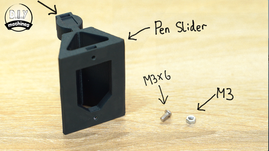
- PenSlider.stl
And the following hardware for this first part of the Y axis assembly:
- M3 Nuts (x2)
- M3 x 6 Bolts (x2)
- 35cm Chromed Rods - 8mm diameter (x2)
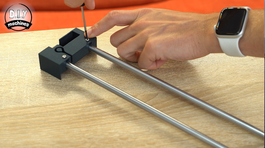
We will start the assembly by inserting two M3 nuts and two M3x6 bolts into the end of the Y-Servo-Housing printed part. Don't fully tighten the bolts just yet, they only need to be threaded in far enough to hold onto the nuts.
Take the two metal rod and insert them into their respective holes ensuring that they are pushed all the way in. The bolts can now be tightened to firmly grip the rods. Don't over tighten them as you may damage the printed part. You can check the strength of the grip on the rods by gently trying to pull the printed part away from the rods.
The two steel rods can then be inserted into the linear bearings on the platform. Take great care to insert them as straight as possible or you may dislodge some of the ball bearing from inside them which will reduce their effectiveness.
Slide this assembly all the way in. When the printed part meets the platform you should here a click as it engages the contact switch.
Step 13: Y Axis - Part 2
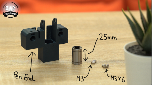


For this step you will need the following:
- M3 Nut (x3)
- M3 x 6 Bolt (x3)
- 25mm long linear bearing (x1)
Slide the linear bearing into is cylindrical recess in the 3D printed assembly. Push it in as far as it goes. It should finish flush with the printed part.
Add the two M3 nuts into the slots followed by the M3 x 6 bolts from above ready to grip the rods as we did in the previous step.
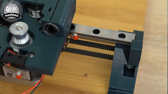
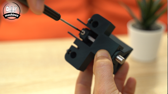
You will also need to add an M3x6 bolt and nut into the top back of the pen slider as pointed out by the arrow in the 5th image above. This is for use in the next step.
Step 14: Y Axis - Part 2

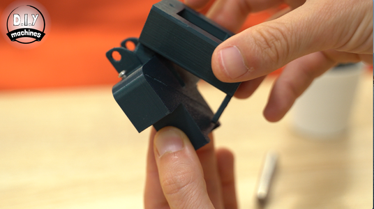

To bring this pieces together you will need:
- 55mm length of 8mm chromed steel rod.
Take the end with the nut and bolt we just added and position it over the slot in the other printed part. You should then be able to gently and firmly encourage the base of the print around the chamfered corner at the bottom of the print. (Check the images for a clearer demonstration of what I'm trying to explain).
At this point the 55mm chromed rod can be inserted from below. Push this all the way into its recess at the top and then secure the bolt to hold it firmly in place.
You should now be able to slide this assembly up and down freely. If there is some friction in yours you will need to reduce it by separating the two printed parts and rubbing some fine grit sand paper over the points of friction.
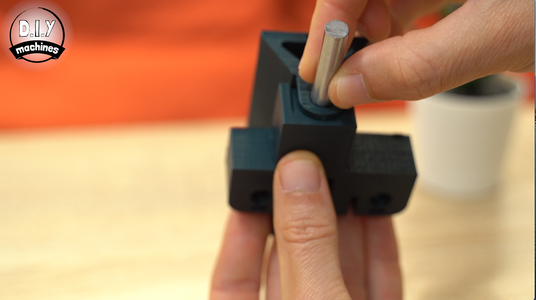
Step 15: Y Axis - Part 3
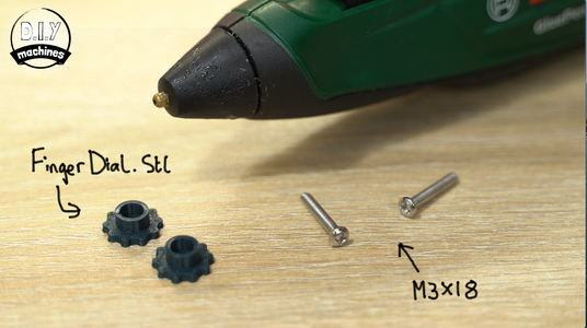


We can now glue an M3 x 18 bolt inside each of our two 3D printed finger dials.
Once the glue has set we can then add this to the assembly by inserting an M3 nut into the holes at the top and bottom of the pen slider which are then held in place by the bolts which now have finger grip dials attached to them.
Our sub-assembly can then be added to the main assembly by fitting it the other ends of the two main rods and tightening the bolts as we did at the other end of this axis.
Step 16: Y Axis - Part 4


You're going to need:
- 50cm length of GT2 timing belt
- Idle pulley with 5mm internal diameter
- M5 x 25 bolt (x1)
Attach one end of the 50cm long timing belt to the top of the pen holder ensuring that the smooth side is attached to the print.
Fit the remaining idle pulley to this end of the Y axis by inserting the bolt through one of the extensions on the top of the assembly, then through the idler and finally out through the other side. The belt can then be passed over the top of the idler and left for connection later.
Step 17: Connect Y Axis to Its Stepper Motor


You will need:
- 60cm long length of GT2 timing belt 6mm wide (x1)
Take one end of the belt, and just like we did for the X axis, create a small loop so that teeth at one end lock together. Push this loop around the V shaped pin found on the top of the Y Axis assembly we have just been working with.
Take the other end of the belt and feed it under the bridge on the main platform and around the stepper motors pulley in an anti clockwise direction.
Head back out under the tunnel and then make another 180 degree turn around the idler wheel this time.
Now take the end of the timing belt towards the un-connected end of the Y axis, make another loop on the end by folding the toothed side of the belt back on itself and pass this around the pin on the top of the printed part.
As with the other axis it is important to get the tension of the belt correct. You can check this again by using your fingers to turn the stepper motor pulley around in both directions. This should not be too difficult to do by hand, if it is then the belt is probably too tight. If you can observe a delay when you change direction before the axis itself does then the belt is probably too loose.
Don't worry too much, this can still be tweaked later on in the projects build if it become apparent that it needs adjusting.
Step 18: Completing the Z Axis


To complete work on the Z axis you will need:
- Mini servo (x1)
- Electrical wire
- 3D printed 'servo arm'
Cut the plastic connector off the end of the servo cable.
Solder three new lengths of wire onto the existing servo wires to make each up to being 55cm long in total.
Wrap some insulation tape or heat shrink tubing around the solder joints to help prevent them from shortening on one another or breaking due the repeated strain of the CNC machines movements.
We can now attach the 3D printed servo arm onto the servo by pushing it firmly onto the servos cog. To check it is fitted at the ideal angle hold the servo so that the wire is exiting out the top. Gently and slowly turn it clock wise until some resistance is felt. The arm should be removed by pulling it off the servo cog and then re-attached so that the arm is in the 5 minute position.
You can then lower the servo into position at one end of the Y axis.
Step 19: Connecting the Servo to the Pen Slider


Take the belt coming from the pen slider and ensure that it is passed over the top of the idler wheel. The other end of the belt is then (you guessed it by now) folded back on itself and inserted between the two fingers of the servo arm.
For the correct distance to be set, the pen slider should be raised when the servo arm is gently turned away from the pen end of the Y axis. But more importantly, it should be fully lowered with a little slack in the belt when the servo arm is pointing upwards. We will be able to check this again in a later step so don't worry if your not yet sure if you have the tension/length correct here.
The slack in the belt helps to ensure that the combined weight of the drawing tool and assembly keep a consistent pressure on the workpiece whilst also allowing it to react to small changes in height of what it is drawing on under the weight of gravity.
Step 20: Electronics Housing - Power Barrel


For this stage of the project you will need two more 3D printed parts:
- ElectronicsHousing-Lid.STL
- ElectronicsHousing.STL
Other hardware you'll need:
- Barrel Connector
- Electric wires
Adding a DC barrel connector to your machine is an optional step. I added it to mine so that I could easily unplug and relocate the project when it's not being used or when I want to use it somewhere else. If you don't want to add one you can just pass your power wires straight through the hole which I will be explaining how to add a connector to now.
Start by soldering a 12cm length of wire to the bottom most leg of the barrel connector when looking at it from behind. Solder another 12cm wire to the leg on right hand side when looking from the back as well.
Step 21: Electronics Housing - Fan and Fixing


For this step prepare:
- 30mm 5v fan
- Small wood screws (x3)
Adding a fan to the housing is essential to help keep the Arduino, and more importantly, the stepper motor driver boards cool during operation.
Feed the fans wire from the outside of the housing towards the inside of the housings tear dropped cut out. Then position the fan so that its wires are passing through the squared of corner of the circle. We can then use the included bolts to secure the fan through the three holes in the other corners of the fan.
We can (optionally) now fix the housing to our base board. Ensure that the where you place it is close enough to each of the axis that the cables can reach to their contact switches, motors, and servos as well as not obstruct the movements of the machine during use. Take a look at the images above to see where I have chosen to position mine.
Use a drill to create some pilot holes through the three countersunk holes in the base of the enclosure. This can then be secured with three small wood screws.
Step 22: Fitting Arduino


For this you'll need:
- Arduino Uno
- M3 x 6 bolts (x2)
Lower the Arduino into the housing with its barrel power connector closest to the one which we have installed and then use a couple of the bolts to secure it in place though the pre-made holes in the Uno.
Step 23: Fitting Stepper Driver and CNC Shield


For this step, the hardware to gather is:
- TMC2208 Stepper drivers (x2)
- Arduino CNC Shield (x1)
Your motor driver board may come with the heat sinks already attached (as shown on the right in the first image above) or you might need to attach it yourself. To do this remove the plastic from the self adhesive pad on the bottom of the heatsink and then firmly place it onto the large copper area in the middle of the board whilst ensuring it does not short any of the other pins on the board.
These then need placing onto the relevant slots for our X and Y axis on top of the CNC shield. They should be identifiable by large capital letter just besides the lower right of each pair of female headers. The X and Y should be the top two when looking at the shield from above.
You will also need to ensure that the pins marked as 'EN' (for Enable pin) are aligned with the same marked pin on the CNC shield.
The wires going from our barrel connector are connected to the screw terminals on the CNC shield ensuring that the correct polarity is followed.
The wires coming from 5V fan are connected to the respective 5V and GND (ground) connections found behind the power screw terminals on the CNC machine.
Step 24: Connecting the Contact Switches and Servo


There are several ways of connecting the wires from the contact limit switches to the CNC shield. You could solder them directly to the pins for a more permanent connection, or like me, you can add a female Dupont style connector to the ends of the wires and push fit them.
If you would like to do this I have made a separate guide on Instructables covering creating your own Dupont connectors which can be found here: https://www.instructables.com/id/Crimping-Dupont-...
The wires coming from the limit switch on the X axis (mounted beneath the raft) should first be threaded through the large hole underneath the letter D on our 3D printed lid. Connect the wires to the white and black coloured pins adjacent to the label 'X-' on the side of the CNC shield. It does not matter which way round the wires are connected for each switch.
The wires for the Y axis contact switch (this is the one fitted on the top of the moving platform) are also passed through the same hole in the lid but are connected this time to the white and black pins adjacent to the 'Y-' label on the shield.
The servo wires also go through the sae hole in the lid.
- The orange wire from the servo connects to white pin adjacent to 'Z+'.
- The brown wire connects to GND.
- The red wires connects to the 5V adjacent to GND.
Step 25: Connecting the Stepper Motors


The Y axis stepper motor (this is the one underneath the moving platform) is passed through the centre hole in the lid and is then connected to the row of pins besides the driver for the Y axis on the CNC shield. The red wire on the bundle coming from the stepper motor should be closest to the outside edge of the board.
The X axis stepper motor cables (this is the one attached to the board) is passed through the currently unused hole in the lid near the centre. Just like the Y axis connection, this one is connected to the row of pins besides the X axis stepper motor driver with i's red wire should also be the closest to the outside edge of the shield.
Step 26: Finishing the Electronics


- You'll need four M3 x 6 bolts for this step.
The CNC shield can be fitted onto the Arduino by carefully aligning the pins between the two and pushing them firmly together.
The lid for the electronics housing can be positioned over the electronics enclosure whilst ensuring that none of the wires become trapped. Use four M3 x 6 bolts to hold it in position.
Step 27: Installing GRBL Onto the Arduino Uno


GRBL is some free open source software used to control CNC machines. You can find out more about it here: https://github.com/gnea/grbl
The machines it was designed for usually feature a spinning head (such as a wood cutter or drill bit) or a laser. We will use a modified version of the software that is able to control a servo which we are using to raise our pen up and down.You will need to download the modified GRBL software, called Mi-GRBL, for this and copy into your Arduino IDEs library folder.
You can download the modified GRBL from here: https://github.com/DIY-Machines/CNC-DrawingMachin...
On a Mac the Arduinos library folder is usually '/Users/'your name'/Documents/Arduino/Libraries' and on a windows machine it is usually found in 'My Documents\Arduino\libraries\'
You can now open the Arduino IDE and head to 'File' -> 'Examples' -> 'grbl-mi' -> 'grblUpload'
Select the correct board type (Arduino Uno) and port after connecting your Arduino to your PC via USB and upload the code.
If you then open the serial monitor we can check that GRBL has uploaded correctly by setting the baud rate to 115200 and sending the command $$ to the Arduino through the serial monitor. If all is well it should reply with its current configuration settings.
Step 28: Configuring GRBL


We will upload a set of configuration parameters to GRBL based on the construction of the plotter as I have laid out earlier in the guide. If you have used different lengths of rods and/or rails then the settings will need to be modified from the following:
$0=10 (step pulse, usec)
$1=25 (step idle delay, msec)
$2=0 (step port invert mask:00000000)
$3=0 (dir port invert mask:00000000)
$4=0 (step enable invert, bool)
$5=0 (limit pins invert, bool)
$6=0 (probe pin invert, bool)
$10=3 (status report mask:00000011)
$11=0.010 (junction deviation, mm)
$12=0.002 (arc tolerance, mm)
$13=0 (report inches, bool)
$20=0 (soft limits, bool)
$21=0 (hard limits, bool)
$22=1 (homing cycle, bool)
$23=3 (homing dir invert mask:00000011)
$24=200.000 (homing feed, mm/min)
$25=1500.000 (homing seek, mm/min)
$26=250 (homing debounce, msec)
$27=5.000 (homing pull-off, mm)
$100=40.000 (x, step/mm)
$101=40.000 (y, step/mm)
$102=250.000 (z, step/mm)
$110=10000.000 (x max rate, mm/min)
$111=10000.000 (y max rate, mm/min)
$112=500.000 (z max rate, mm/min)
$120=100.000 (x accel, mm/sec^2)
$121=100.000 (y accel, mm/sec^2)
$122=10.000 (z accel, mm/sec^2)
$130=250.000 (x max travel, mm)
$131=300.000 (y max travel, mm)
$132=200.000 (z max travel, mm)
To apply this to your machine you can copy a paste each line one-by-one and send them through the serial monitor. Once done, sending $$ again should show you the same configuration as above (as opposed the GRBLs default values).
These settings are saved to some non-volatile memory on the Arduino so you will not need to send the configuration every time you turn the Arduino off and back on. (Thankfully).
Step 29: Homing for the First Time


Before we begin to test the hardware, gently and slowly, manually move the drawing head of our machine to roughly in the centre of the drawing area.
Connect the power supply to our electronics housing.
As we have added contact switches to our machine, when it starts up it will start in an 'Alarm' state. This is because it cannot yet be sure of where its axis are positioned along the length of the travel.
To resolve this we will issue the homing command (not yet!) of $H. This will tell the GRBL to move the machines head slowly towards the lower left corner of the drawing area until each axis has made contact with the limit switches. Once it has made first contact with them it will perform a small bounce to help improve accuracy. We will then see 'OK' in the serial monitor.
If, when you issue the command, your machine does anything other than this - such as an axis moving in the wrong direction etc, be prepared to disconnect the power. You should then check your work against the first video and the instruction preceding this step in this written guide. You can also find an FAQ section section on my website www.diymachines.co.uk where I will try to answer any common problems that arise.
Now issue the command $H.
Step 30: Testing the Servo and Steppers


To test the servo, issue the command 'M3 S90' in the serial monitor followed by 'M5'. You should find that when you send 'M3 S90' the servo should tug on the length of timing belt which will then in turn lift the slider up. 'M5' should lower the slider by turning the servo back in the other direction.
When lifted, the pen slider should be up close to being nearly at the end of its available travel. If the servo is continuing to try and lift the slider further (which you would hear) than you should adjust the timing belt by increasing its length until the servo stops struggling.
Once the servo is OK we will re-issue the homing command $H, and this time once the homing is complete issue the command 'G92 X0 Y0'. This tell GRBL to set the current location of the head as being the origin by resetting the X and Y positions in its memory to 0.
To test the stepper motors we can issue the command 'G1 X10 Y50 F2000'. Let's break down this command:
- G1 - Tells GRBL to move in a linear fashion (a straight line as approved to a curve for example)
- X10 - Move to 10mm from the origin on the X axis
- Y10 - Move to 10mm from the origin on the Y axis
- F2000 - The speed at which to move. F stands for 'feed rate'.
Step 31: Using Chilipeppr


To help us create more detailed drawing we can use a GCODE sender (GCODE is the name for the instructions that tell GRBL how to move) to feed hundreds if not thousands of lines of GCODE to our machine. For this we will use a fantastic web application called Chilipeppr.
You'll find it on http://chilipeppr.com/grbl . I recommend using Google Chrome for this.
The first thing we need to do in order to use Chilipeppr in the browser is to install a small JSON program which will allow our web browser to connect to the Arduino through the USB port. There is a link in the lower right hand side to a page which explains how to download and install the JSON server (which is available for Windows, Mac and Raspberry Pi's).
Download Serial Port JSON Server: https://github.com/chilipeppr/serial-port-json-server/releases
Once done we can go back to the Chilipeppr window and reload the serial port list using the circling arrows towards the lower right (see the second image above) and then select the 'GRBL' option and speed of 115200. Finally check the box next to the Arduino Uno which tells Chilipeppr to send the GCODE to this device.
Moving to the Axes window at the top right, we can press the 'Home Axis' button to trigger the same homing sequence as earlier, followed by the 'Zero Out' to reset the coordinates. This does the same as issuing $H followed by G92 X0 Y0 did earlier. In fact, you can see it doing this in the Console found in the lower left corner of the workspace.
Step 32: Doing a Dry Run


Before we arm our project with a pen we'll do a dry run first. Download the test file 'DIYM-Test.gcode' from my Github page. Drag and drop the downloaded file onto the centre area of the workspace preview to load the file.
Press the play button the left hand side to beginning streaming the instructions for this drawing over to your Arduino.
You should see your Arduino try to draw the illustrations shown on the screen. If all went well, it's time for the next step.
Step 33: The Machines First Drawing


Tape down a sheet of paper onto the backboard. I used some insulation tape in each of the corners.
To add the pen you will need to open the passage for the pen by turning the two thumbscrews anticlockwise.
If your pen slider is not currently in the raised position you can achieve this by issuing the command 'M3 S90'. Insert the pen so that the writing tip is about 3 to 5mm above the surface of the paper when you tighten the two thumb screws.
Home and Zero out the axis again just encase we jogged the arm. I have gotten in the habit of doing this every time I change the writing tool. You can then press play and watch in awe at what you have achieved so far. :)
Step 34: Creating Your Own Drawings - Inkscape Prep


We can create drawings for the machine using Inkscape. Specifically version 0.48.5. This can be downloaded from here:
https://inkscape.org/release/inkscape-0.48/?latest...
After it has been installed we will add an extension to it designed to write GCODE in a way our machine can understand. The MI Inkscape extension can be downloaded from Github:
https://github.com/DIY-Machines/CNC-DrawingMachine
The four files inside this folder should be copied (overwriting any existing files if a warning appears) to:
C:/Program Files (x86)/ Inkscape/Share/Extension/
Next we can set up the document in Inkscape. Start Inkscape and then head to File -> Document Properties. In the pop-up dialogue box change
- the default units at the top to MM
- in 'Custom size' set the units to MM again
- width to 225
- height to 250
Step 35: Drawing the Artwork and Generating GCODE


To start, we can create a box which is almost the size of our working area. We can then use this to have our machine mark out on the baseboard the extent of its drawing workspace with a permanent Sharpie. Handy huh :)
To do this, select the box tool from the left hand side menu bar and drag out a box just slightly smaller than the canvas in Inkscape. I measure the thickness of a line made by a sharpie as 0.8mm. We can tell Inkscape this to get a better representation of what our finished artwork will look like.
To do this, open the Stroke and Fill windows using its icon towards the lower right of Inkscape. You can also use the keyboard shortcut: 'Shift' + 'CTRL' + 'f' to do the same. Open the 'Stroke style' tab at the top and set the width to 0.8mm.
Only paths are converted into strokes and GCODE by the plugin. Because of this, once you have added artwork (including any text etc) you need to highlight all the artwork and then go to 'Path' -> 'Object to Path'.
With this done, we can then go to 'Extensions' -> 'MI GRBL Z AXIS Servo Controller' -> 'MI GRBL Z AXIS Servo Controller..' to get ready for the GCODE export.
There are several parameter here that we need to update, set them as follows (and also shown in the above images):
- Servo Up: M5
- Servo down: M3
- X axis speed: 10000
- Y axis seed: 4000
- Angle for servo: 90
- Delay: 0.2
- Directory: To wherever you want to save the GCODE file generated
- Filename: Well, to whatever you would like to name the file.
You can then press Apply to generate and save the GCODE file.
Step 36: Sending a Drawing - Recap


To execute the GCODE as before, and for all future drawings, following this set of steps should prevent most errors:
- Load the GCODE file into Chillipeppr
- Home the Axis
- Zero out the axis
- Press play - if the dry run goes well.....
- Raise the pen slider by issuing M3 S90 (if you need to).
- Add the writing implement about 3 to 5mm above the surface of the item you want to draw on.
- Home the axis.
- Zero out the axis.
- Press play.
You can follow the above to have your machine draw out the boundary lines we just produced in Inkscape. If
you're confident in your use of the machine you can skip stages 1 to 4 inclusive to bypass the dry run.
Step 37: Final Tips and Ideas


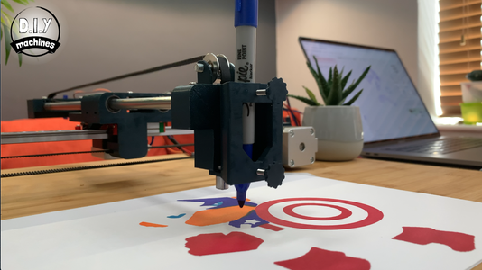
The best way I could work out so far to create a block of colour is to create a pattern of lines going back and fourth in one continuous run. This is how I created the blocks of colour in my Avengers character.
For the multi colour drawings I put each colour for the drawing on a separate layer in Inkscape. You can then save the file and delete all the unwanted layers (hiding them does not seem to work for this). Select the remaining artwork layer, generate paths and then export the GCODE for that colour.
You then use undo to bring back all the other layers. Repeat the steps again leaving a different colour layer and work through each layer/colour one by one. You can then issue the GCODE files to your drawing machine one after the other whilst changing the pen between each drawing. As long as you continue to home and zero out the axis after changing the pen every time you should not experience any issues with alignment.
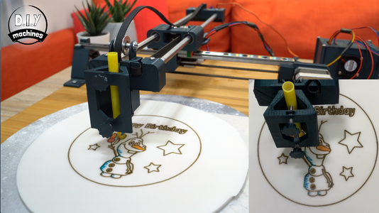
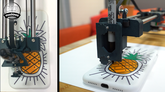
Some idea for use that I have had success with so far include using permanent Sharpie pens on a white silicone phone case to create my own phone case. I also bought some edible ink pens from the supermarket and had it write out a birthday message onto a sheet of Icing which I rolled out (I left it in the open air for a couple of hours before drawing so as to let it harden slightly). This can then be trimmed with a knife and added onto the top of a cake.
Step 38: Project Complete
Gosh, that turned out to be the longest Instructable I think I have written so far! If you made it this far I appreciate you taking the time read it in full. :) Thank you.
If you have any issues with your machine I encourage you to check the comments here, on Youtube and the FAQ on my website (diymachines.co.uk) to see if there is a solution or suggestion already offered.
Should you want to support my projects, please consider subscribing to me on here and Youtube. I also have a Patreon page where some very kind people are helping me to cover the cost of designing, documenting and sharing these projects. Please consider joining them in any way if you can.
A vote in the CNC competition would also be very much appreciated.
Until the next project, ciao for now.
Lewis

Second Prize in the
CNC Contest 2020


